Thursday, 18 August 2011

Chapter 10 - In which I cheat a little, and things get back on track

Things are starting to look up - I now have all of the parts I need to finish my reprap, with the exception of some hot end bits (I think). The major cause of the delay was bought on by myself. In a bid to reduce the cost and number of surplus fixings I'd be left with, I opted to purchase the majority of the components I need through the company I work for. We use a vast array of fixings and electronic components, and I was able to get hold of almost everything I needed. Placing the order, and picking all the parts too longer than expected, but now it is all done I can crack on with the build.

Here are the majority of the parts I purchased:

Mechanical parts
Electronics
The microswitches in the first picture have 90 degree arms on them, and will need to be modified before use as endstops. They were more expensive than most of the others I looked at on the web, but they are good parts. They're UL and CSA approved, and are rated to switch 15 Amps. Whilst I'll never need that much, it provides a margin for error, especially if I end up with a firmware that doesn't use the processor's internal resistors. Speaking of processors, I purchased that too but haven't got a photo yet.

I got back to work by attaching the Y axis stepper motor. We don't carry M3 by 10mm screws at work, so I got 12mm long ones instead. I knew that the motor screw holes bottom out and that 12mm would be too long, so I got some spring washers to take up the slack.
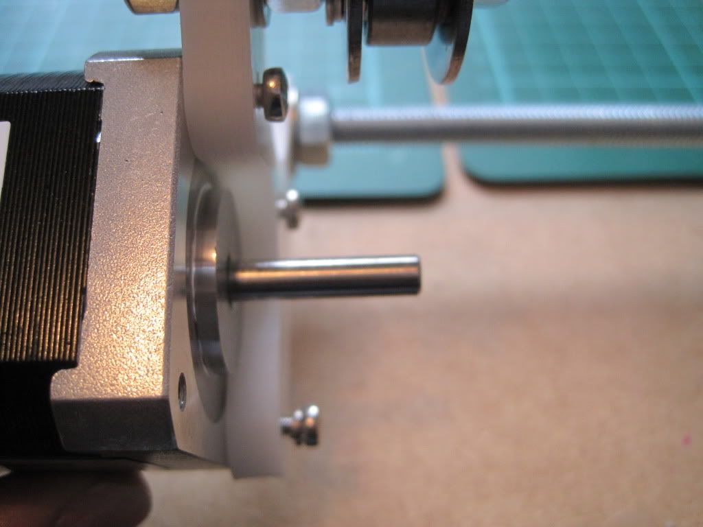
The screws fully seated - you can see the slack caused by them being too long. The bottom screw has the spring washer fitted.

Next I fitted the pulley to the motor shaft. I had gotten a couple of pointy grub screws, thinking that flat ended ones wouldn't grip the shaft well, but hadn't looked at the screws Nophead had supplied. These turned out to be pointed as well, so I kept them (thanks Nophead!). I aligned the pulley with the bearing and tightened it into the shaft before checking that it gripped well and didn't turn. At the same tie, I moved the Y axis bearings closer to the middle of the frame. They were a way off to one side, and I was worried about off-centre forces affecting the movement of the axis. I brought them as close to the centre as possible.
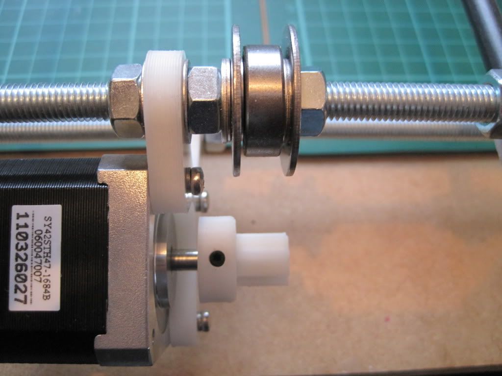
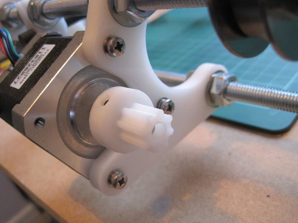
I realised I had forgotten the plain washers behind the spring washers. I went back and fitted them.

I wrapped the Y axis belt (the shorter of the 2 supplied) around the bearings and lined it up over the lower sheet. I marked where it lay on the sheet, and started to carefully remove the sheet form the Y axis smooth rods. Then, disaster! - the bushings came off. Whilst the superglue had done a good job of holding it while it was flat, it cracked when I started to move it vertically.


I took the sheet off completely and used the opportunity to mark up the clamp holes and drill them.
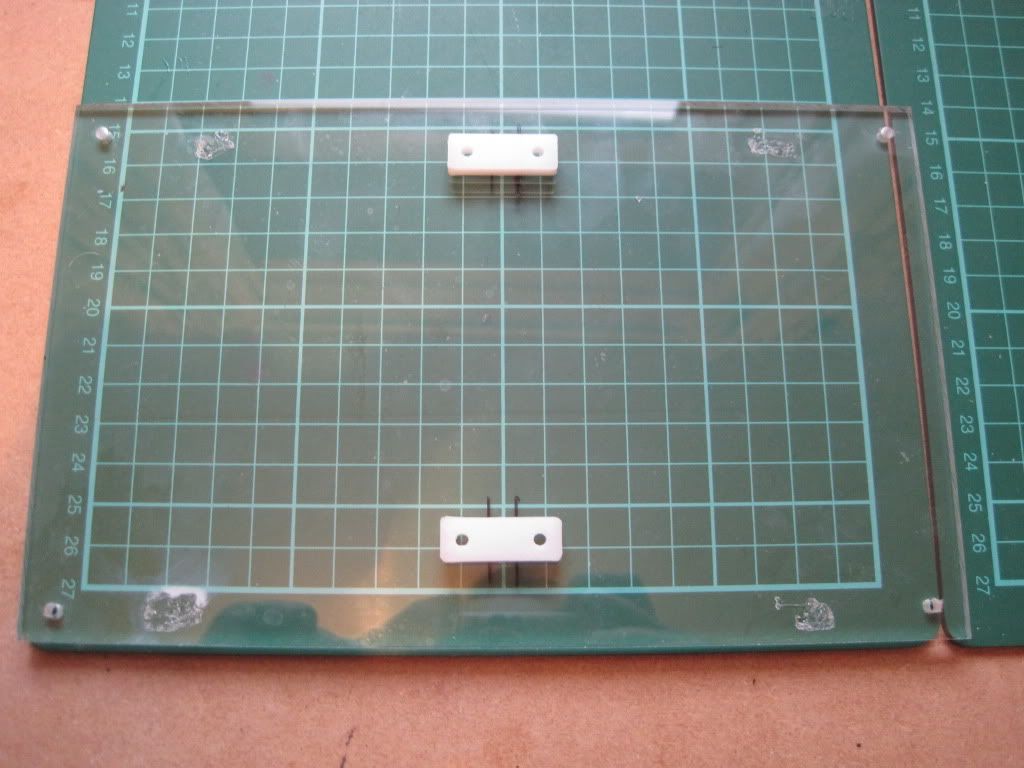
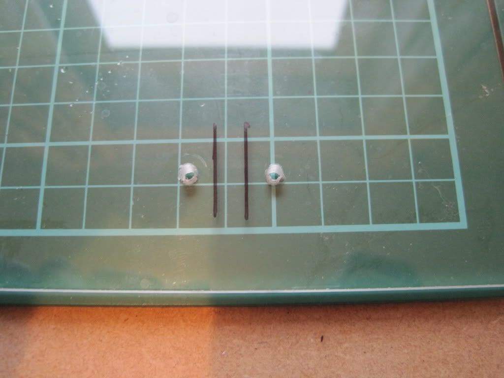

I glued the lower tray down to the bushings again, and will continue with the fitting and tensioning of the belt when the glue is dry. The only good thing to come of this is that the movement seems a little smoother now I've reglued it. Perhaps the bushings were misaligned when I fitted them initially.

Whilst waiting for the glue to dry, I figured I'd make a start on the X axis. Here are the ends:
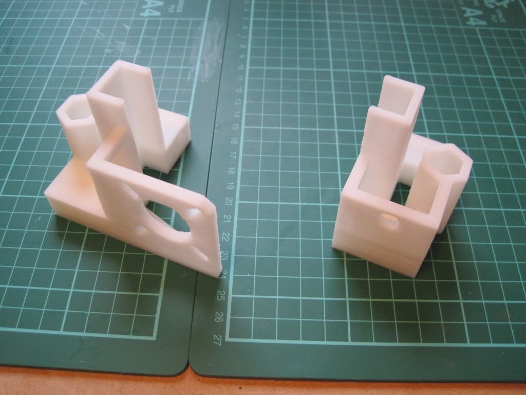

The holes are all the right size, so no need to drill anything out. I fitted the nuts into the traps, which was a little fiddly. I used the end of a file to make them lie flat when needed:


I fitted M3x12 screws into the nuts (again lacking in 10s). These seem excessive (although they may have something important to do later), and I think that M3x8 or even 6 would be better.


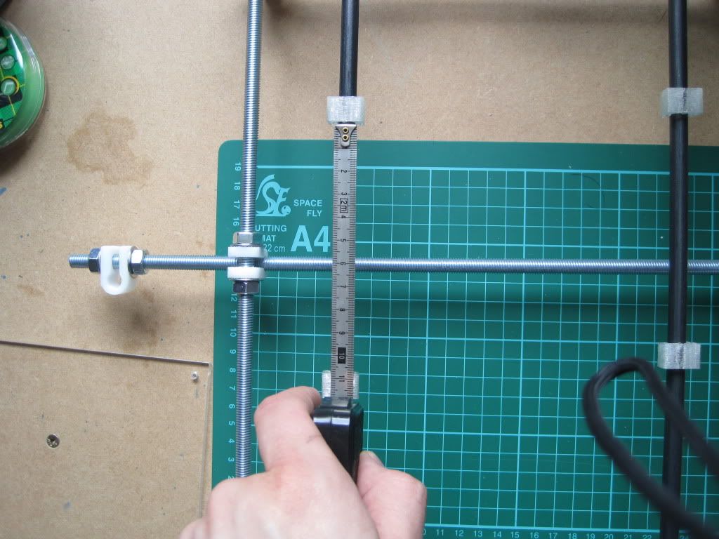
The visual instructions say to lay the parts out 500mm apart, but for the suggested X axis smooth rod length of 420mm this was too far:


Anyhow, I fitted the X ends to the rods, and tightened the screws:
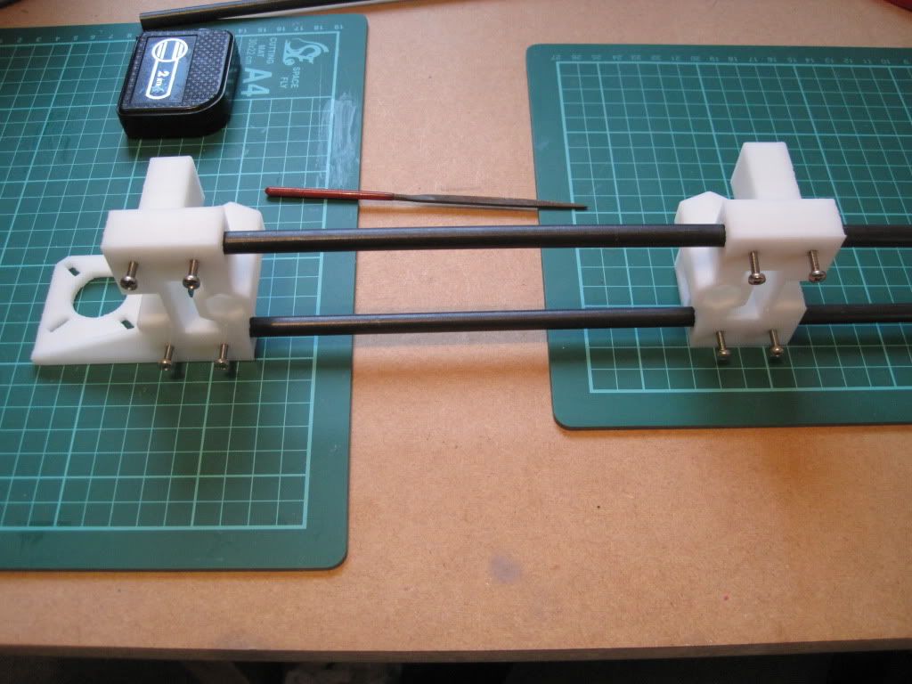

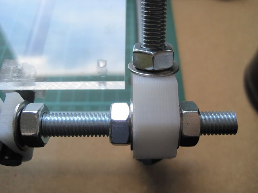
I built the X end idler bearing onto a 50mm piece of threaded rod, and fitted it, and that's the X axis done for now:
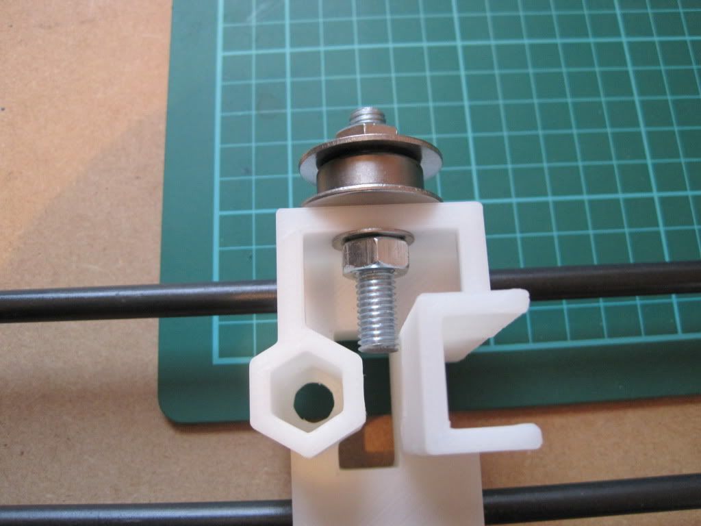

The next job is to level the printer. Mine was a bit wonky:
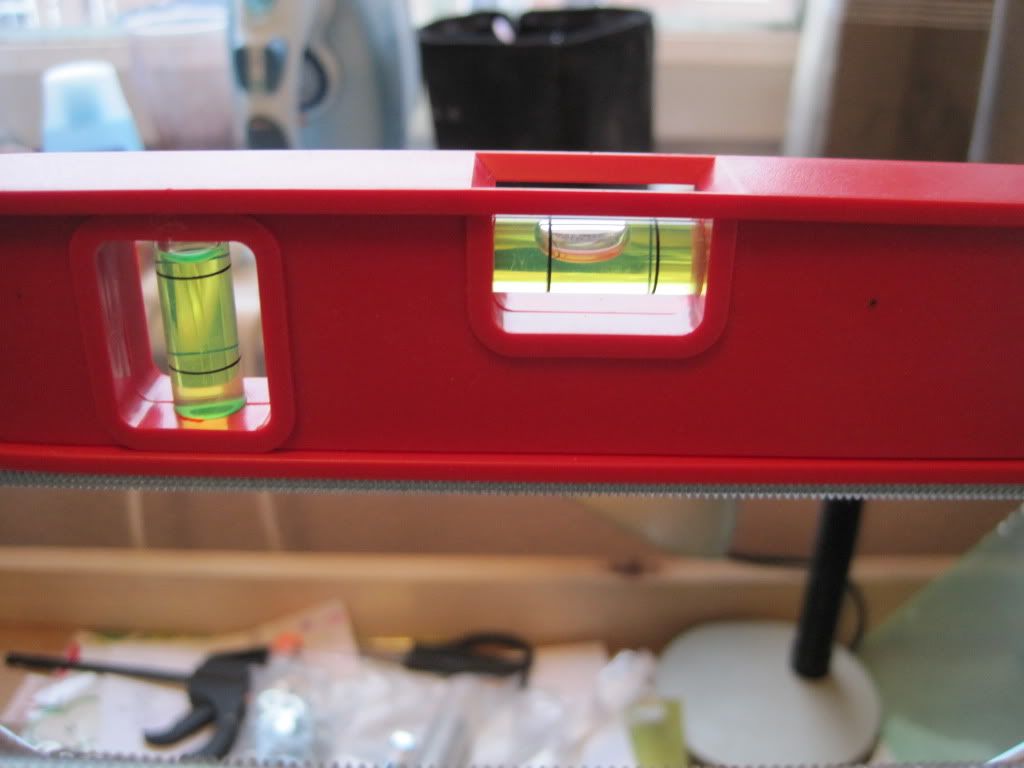

A pair of plastic rules provided the bulk of the adjustment required, with folded post-it notes providing the fine-tuning.

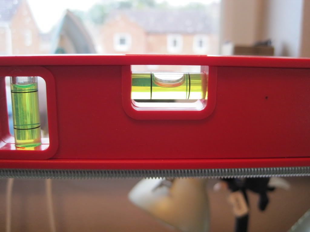
After adjustment - nice and level.

I have a snap-on adjustable foot in mind as one of my first upgrades....

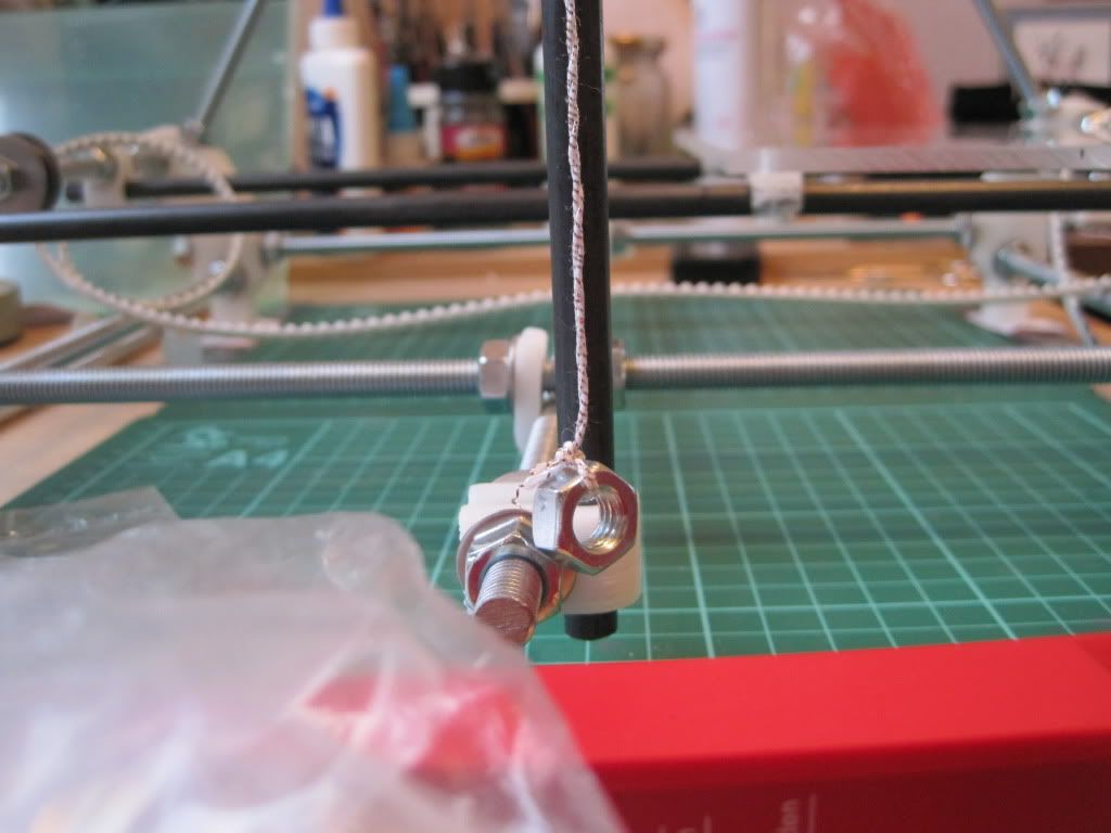
The preliminary adjustment of the Z rod fixings went well, and I moved on to the upper fixings. I fitted up M3x25 screws as suggested in the assembly instructions, but found they were too long. I hadn't read far enough ahead to spot the note about this! I was on the brink of turning the screws around and trying them in reverse, when I looked back at my parts list. I realised I had gotten the correct amount of 20mm screws, so I replaced the 25s and the rod restraints now fit well:
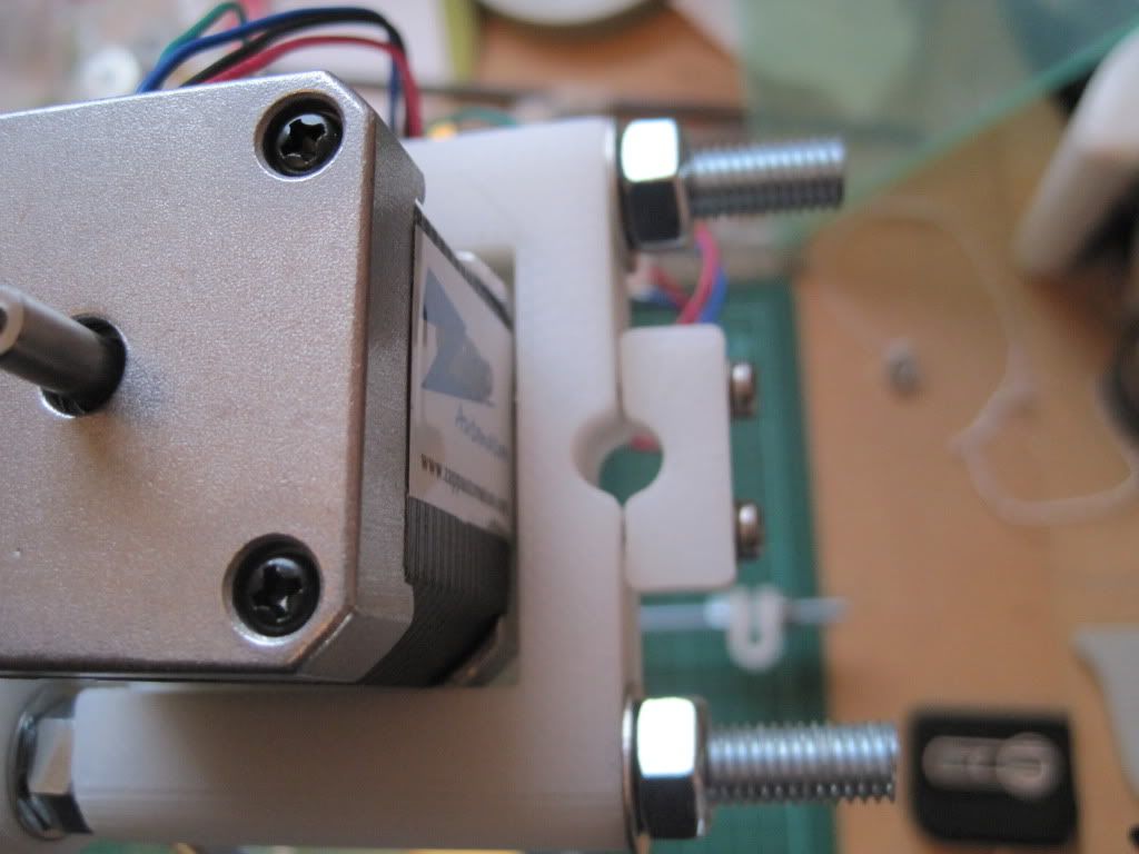
I test fitted a motor to make sure the screw threads didn't protrude too far - they don't.
The last part of this evening was spent fitting the z rods and checking them for verticality. It was a slightly painstaking process, but well worth taking time over.


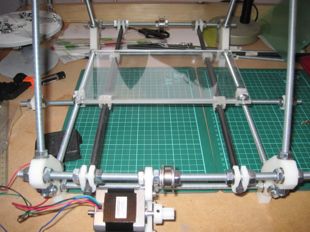
So here is the machine after all of today's exertions. I'll let the glue dry overnight, and hopefully tomorrow will see the mounting of the X axis.
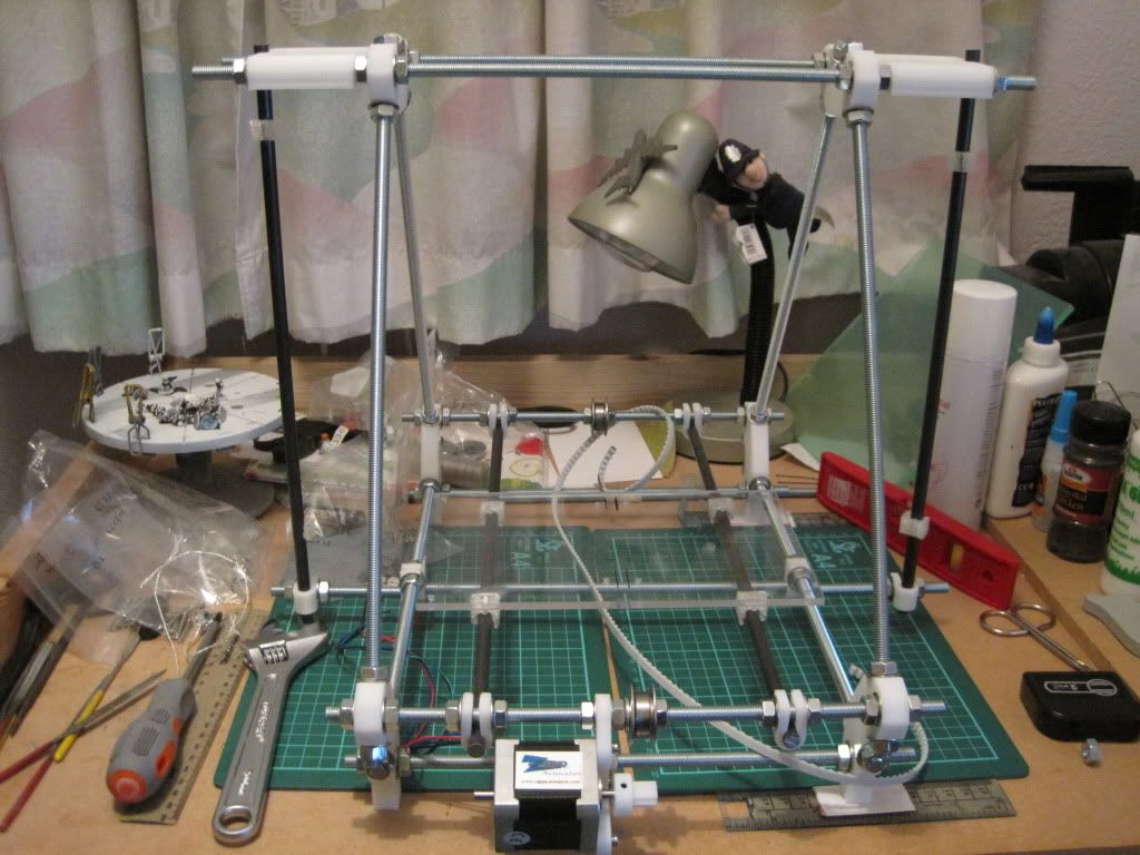

Next up: X's, Z's and leadscrews!

Wednesday, 3 August 2011

Chapter 9 - In which things actually start to work

I'm still waiting on more parts before I can resume building. I have however been back on ebay, and bought even more bits and pieces. I picked up the resonator I need for the sanguiniololu, and finally ordered the stepper drivers. I went for stepsticks in the end, from this gentleman in Hong Kong. At around £8.60 each with free shipping, they are definitely worth it. Hopefully they won't take too long to arrive.

In the meantime, I have been working on the laptop again. I made another mistake yesterday, and tried to update the virus killer to the latest version. It only took two attempts and some 4 hours!

After the dubious amount of success I had with skeinforge and python, I decided to try an easy-to-install option next - RepRap Host. It turned out not to be so easy after all -

I found the page on the wiki, and started downloading what I needed. I went and got the latest version from Github, and unzipped it. The wiki mentions a .BAT file that launches the program, which should be visible in the root directory. I went to look for it, and it wasn't there. A quick search revealed it was hiding in a sub-folder (lib/system-dependant/windows-I586). running it however resulted in an error (which I forgot to screenshot). Inspecting the error text suggested that the software needed to be moved to "program files/reprap" - I step I had glossed over in the wiki, believing it was for the sake of neatness. However, this location is coded-in, and so I moved the files there and tried again - same error message.

I updated the Java install to the latest version of release 6, and took the extra step of installing the JDK as well, but to no avail - I still got the same error. It appeared not to be able to find the "main" class. I edited the .bat to see if there was a difference between "programfiles" and "program files", which there wasn't.

Getting a bit frustrated by this point, I remembered the wiki page had a link to sourceforge, and an older version of the software. Whilst the sourceforge site is frozen now, the last update is only a couple of months old - it is dated at 9th of May, 2011. I downloaded this version, deleted the github copy and unzipped this to the "program files/reprap" directory.

The .bat file was exactly where it was supposed to be, and a double click resulted in some satisfying activity and the below windows:


Looking good! I loaded one of the test STL's I'd used the other day, but it didn't appear on the build bed whilst a second one did - I suspect that the stl is corrupt.

While I'm glad I have it working, I can't help feeling that there is a simple solution to my earlier problem. I couldn't see any help on the wiki though, nor in the documentation in the GIT download (although I may have missed it).

I'll see how this version of the host works, and if I need to I'll work out how to update it later.

Up next: More building! (Hopefully....)

Tuesday, 26 July 2011

Chapter 8 - In which Bernard comes out of retirement, and I wrestle with snakes

I decided a couple of weeks ago that I was going to run my printer from a laptop. I figured that this has several advantages:

- I can install and play around with as much new software as I like, without fear of damaging my main machine
- I can run the machine and calculate Gcode without it slowing down anything I'm doing on my main machine
- Its portable. I will probably have to move the printer setup from the spare room in the future, so portability is good.

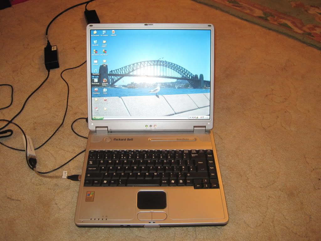
Enter "Bernard":


Bernard is my girlfriend's old laptop, who has been enjoying his retirement shut away in a draw. Not any more - he ought to be just right for what I need.

Since I still can't build any further, I thought I'd get Bernard up and running, and have a look at the various software packages I will be needing. Enter problem number 1 - the screen went blank after a few seconds of being turned on. Adjusting the angle of the screen seems to have fixed it (loose cable I guess) and it hasn't happened again.

I spent some time reorganising some old files, but before I could go any further the screen went black again, and all the lights went out. It was fairly hot too, which lead me to problem 2 - the cooling fan has broken, causing the CPU to overheat and Bernard to shut down.

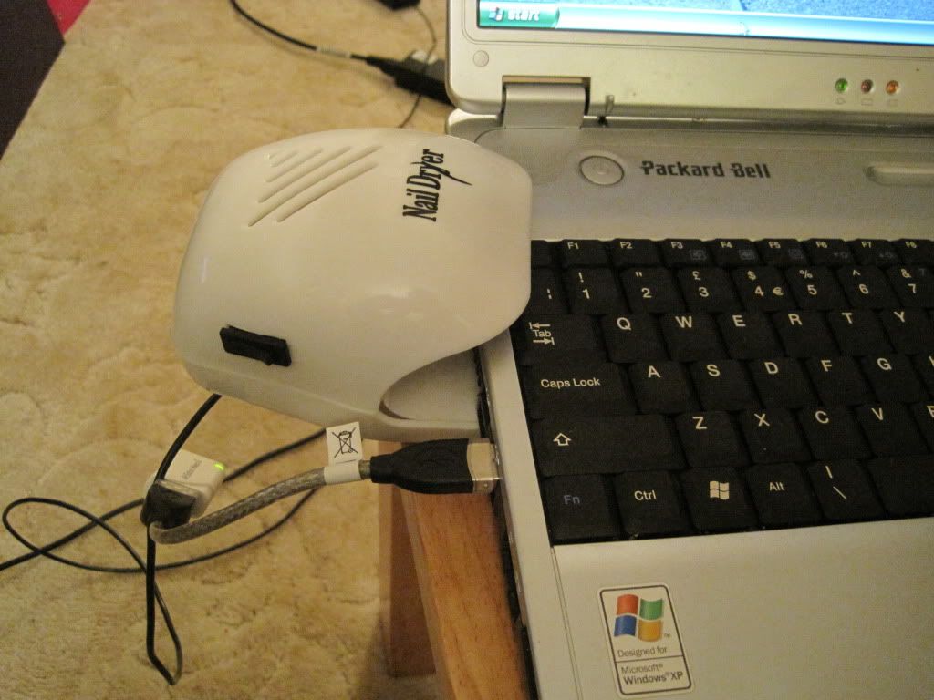
I figured I had just the short-term solution - several years ago I had picked up this nail-polish dryer, and had rewired the push-pad switch to a rocker switch. I had intended to use it to dry the paint on small models, but it was too noisy (and it blew the smallest parts away!). Turns out it was a perfect fit:


I used the nail dryer to push air (backwards) over the cooling fins, and out the bottom of the laptop. I installed a CPU temperature monitor to gauge when to turn the fan on and off.

With the cooling sorted, I pushed on with the next part of the plan - updates. Bernard has been out of use for about 2 years, and so was rather lacking in care packages from Microsoft. The first batch consisted of some 50-odd updates and security fixes, along with a new version of IE. I also updated the anti-virus.

My plan is to have Bernard drive the printer, but do the design work on my main machine. I set up a small network to allow me to share files between the two wirelessly. I will design parts and models, and export them to .stl format before transferring them to be printed.

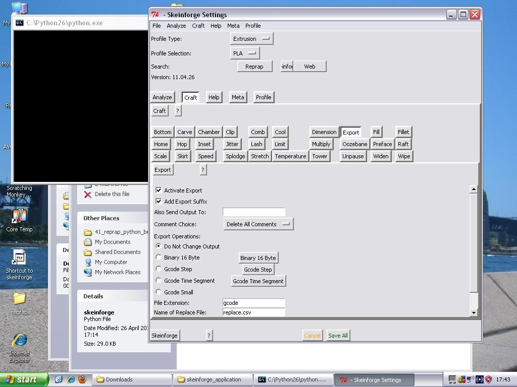
Next I started to look at the software I would need to drive the printer and to generate Gcode. I don't know why, but I started with Skeinforge. I hadn't planned to start out using it, as by all accounts it is very in-depth, with a lot of things to configure, but I must have been reading about it, because I decided to get it working.

Now Skeinforge needs a slightly older version of the Python programming language to run, namely version 2, not the newer version 3. I went off and started to download the latest version of 2.7.  I then went and looked at Psyco, a Python script that can speed up other scripts, potentially doubling the rate of gcode generation.

Psyco hasn't been updated for Python 2.7 yet (and doubtfully ever will be, as development has stopped), but I found a version for Python 2.6. I went off and downloaded the latest build - 2.6.7. After unzipping however, I realised that I only had the source, not a compiled version. I just couldn't work out how to compile it, so I went back and found an older version of python which came compiled - V2.6.6.

I installed Python 2.6.6, Psyco 2.0.0 for python 2.6, and Skeinforge 41, and woohoo, it worked! Overjoyed with my progress, I moved on to the firmware.

The recommended firmware for the Sanguiniololu board is Sprinter. I downloaded the project from github, and went off to get the prerequisites - the Arduino software (version 0018) and Sanguinio addons. I unzipped the Arduino software, and added the Sanguinio expansion as directed in the sanguinio readme. I unpacked the sprinter download, and tried to follow the instructions to build the firmware. While I don't have a board to send it too yet, I figured I could at least make sure I had everything I needed and could make a successful build. Once again I got stuck. The sprinter instructions are all written for linux, and consequently don't make much sense for windows users. I managed to get the firmware to compile in Arduino, but whether it was correct or not is another matter.

It was 2am by this point, and I had had enough. I'll come back to Sprinter when I am closer to needing it, and will most certainly write up what I have to do to make it work!

My adventures were not quite over yet, as the next day I decided to install XP's service pack 3 - this only took about 3 hours! (Time well spent watching the German Grand prix) After rebooting for the umpteenth time, and installing another 54(!!!) updates, I tried to run skeinforge again to make sure everything was ok.

It wasn't. Somewhere along the line, something had gone wrong, and now python crashed every time I launched skeinforge. I removed everything, put it all back on, and still no joy. I removed it all again, and this time installed skeinforge before psyco and tested that it worked, which it did. Adding psyco broke the install again, so I removed it.

I gave skeinforge a test run with a couple of .stl files I had generated some time ago, and it successfully generated gcode. It didn't look right though, and it generated very quickly, so I suspect that the STL's I used are at fault. I'll test something else at a later date.

Just to prove to myself that it works:


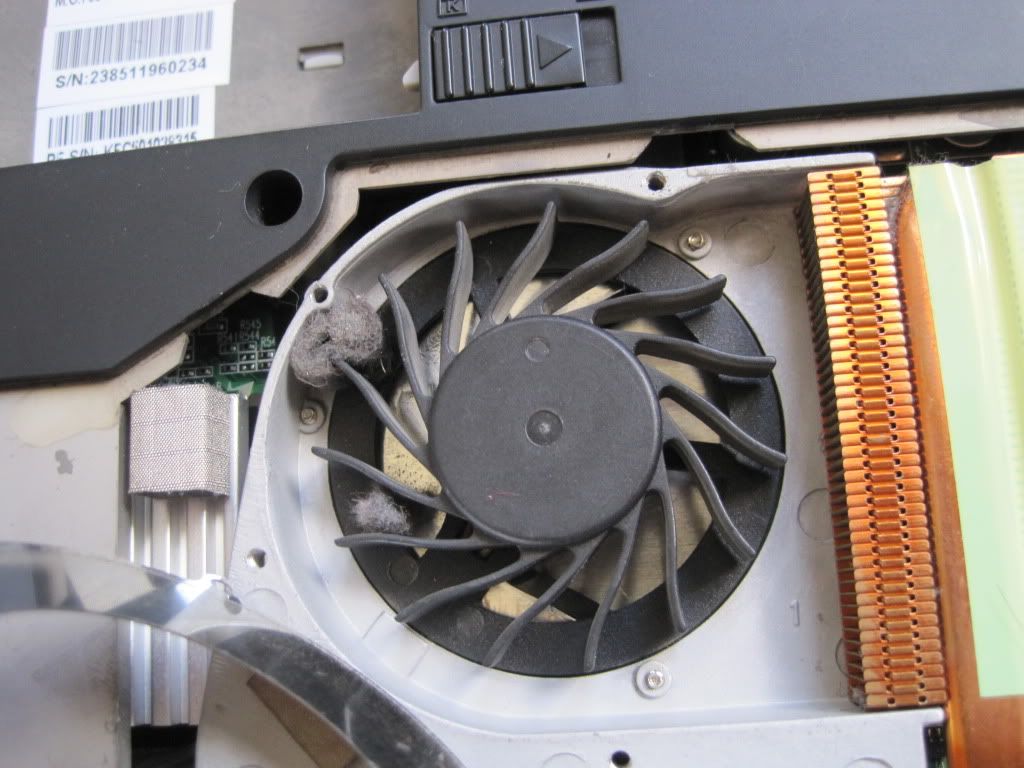
Not being quite done for the weekend, I took Bernard's back off to establish what was wrong with the fan:

http://img.photobucket.com/albums/v31/lsutehall/reprap/IMG_1087.jpg (direct link as blogspot seems not to like the photo)

It was jammed by the most dense fluffball I've ever come across. Fluffball removed, cooling was restored.

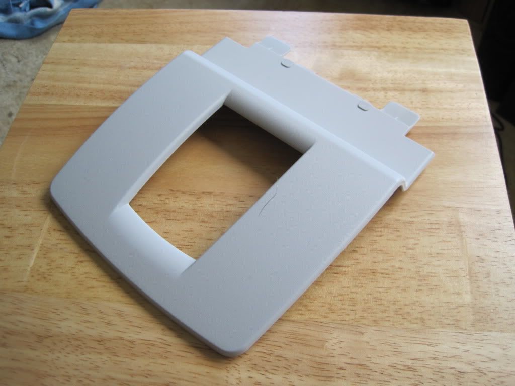
I also found what looks like an old inkjet printer part that ought to do nicely as a laptop stand:


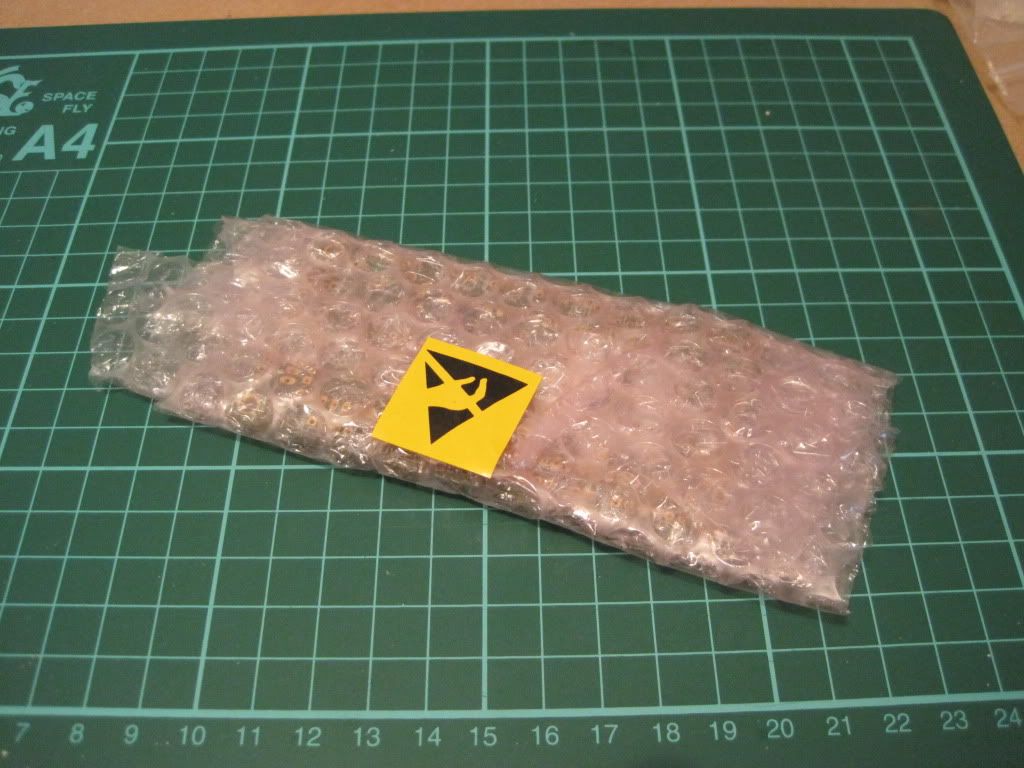
In other news, the Sanguiniololu board arrived last week. I've not removed it from it's bag, as I want to avoid static damage to the chip:


Up next - Installing the java host software.

Sunday, 17 July 2011

Chapter 7 - In which I find a problem

It seems like the superglue is holding, but I haven't tried to remove the bottom plate from the axis yet - I figured I'd give the glue some more time. What I did do however was slide the plate up and down the axis. Primarily this was to check the bushings ran smoothly, but it showed up something else interesting.

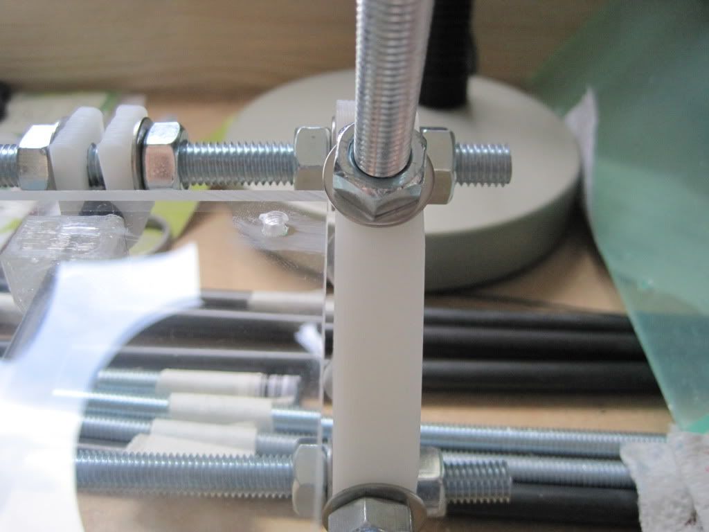
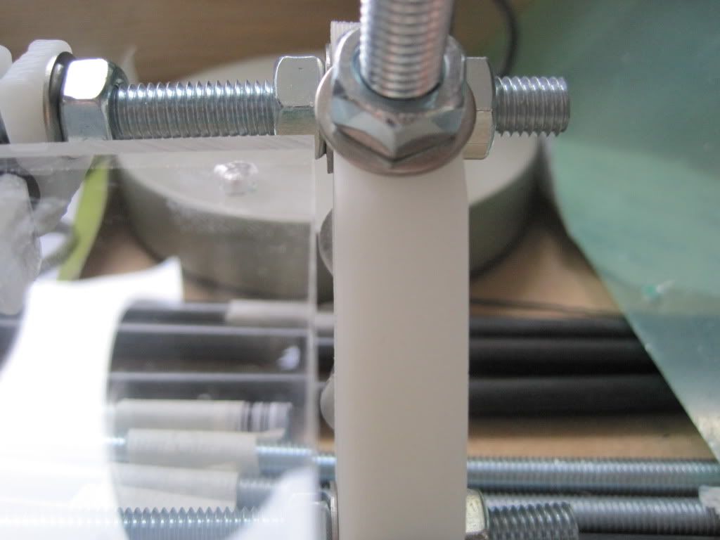
This is the right hand corner of the carriage at the front of it's travel:


This is the back right hand side of the carriage at the far end of it's travel. Note the spacing of the plate from the vertex:


The Y axis is misaligned. I had measured and checked and rechecked the spacing of the smooth rods on the rear rod, but apparently not well enough. Although not a big misalignment (somewhere in the order of 0.5 to 0.75mm), it is certainly noticeable when moving the carriage.

I adjusted both the smooth rods on the rear rod by the same amount, to keep them parallel. This is the rear right hand corner after adjustment:


Much better. This step of checking the alignment is definitely worth it.

Chapter 6 - In which I almost did nothing

I still haven't bought everything I need, especially the M3 screws and nuts that I need to mount the stepper motors and the belt clamps. I was expecting not to be able to do anything this weekend, but after a trawl through my modelling toolbox I found a 3mm drill bit and decided to drill the top and bottom plates.

Here is the bottom plate (5mm acrylic, with the protective film still on). I have marked up the corners at 8mm (the larger dots).


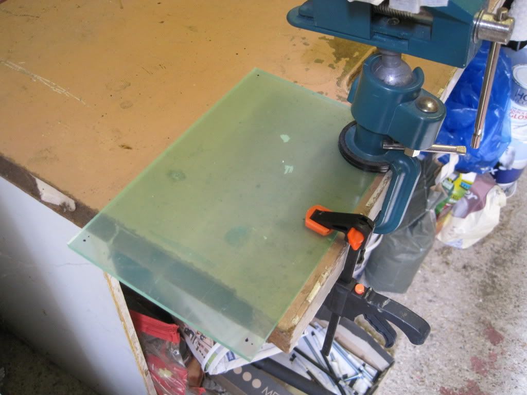
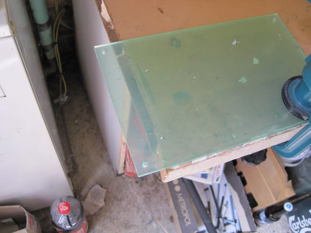
I took it to the garage and clamped it down. I couldn't find my other expanding clamp, so I used the vice to hold to the other end in place.


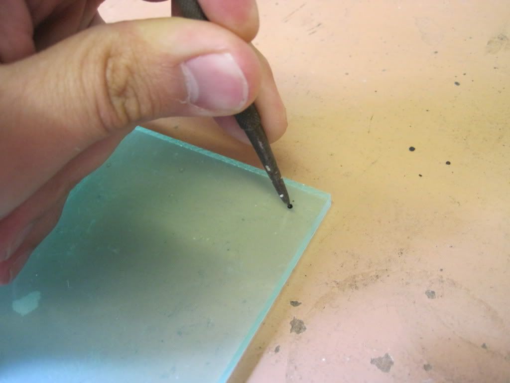
I used a scribe to mark the centres of the holes, and hopefully stop the drill bit from wandering.


I loaded up the 3mm bit and drilled all four corners.


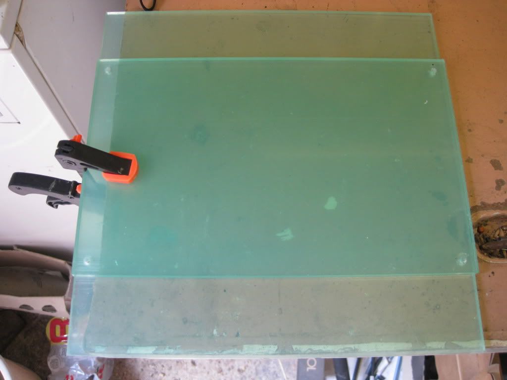
I centred the bottom plate on the top plate and redrilled.


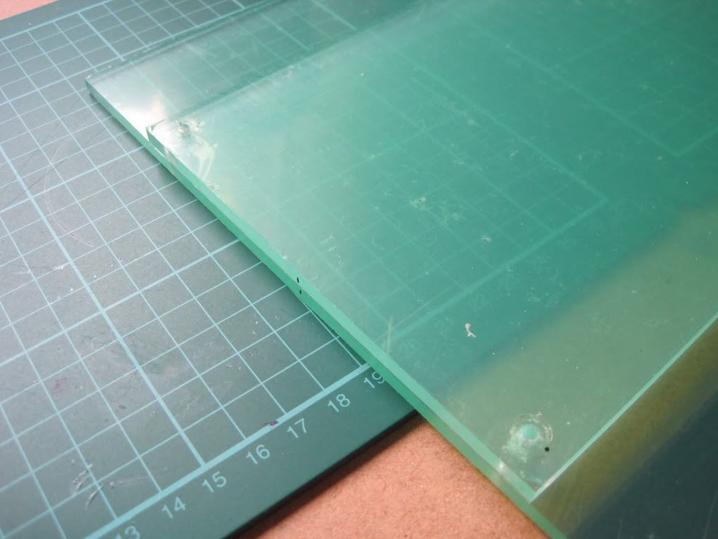
I marked the sides of both sheets, just in case they weren't completely centred when I drilled them. Interestingly, the heat generated by the drilling seems to have melted the protective film around the holes, bonding them together. It pulled apart easily though, with no harm done.


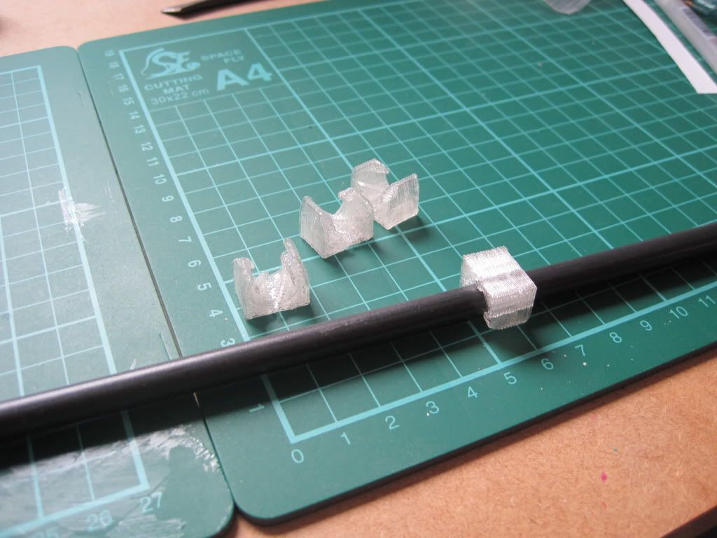
I snapped the PLA bushings onto a long section of smooth rod. They were a little stiff, but a combination of running them up and down the rod and using the heat-the-other-end trick freed them up enough to run smoothly.


I snapped the bushings onto the y axis rods. They were still a little rough running, so I ran them up and down until they were smooth again. I think the smooth rod I am using is not entirely cylindrical. I think it's round enough though, but we'll see.


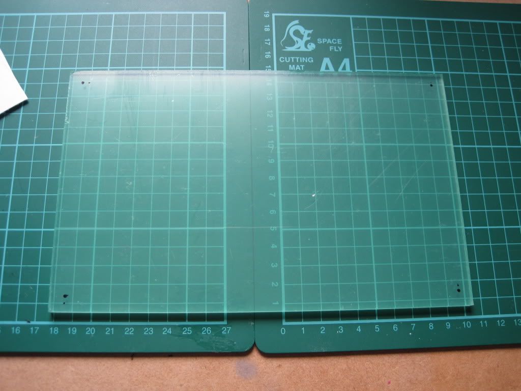
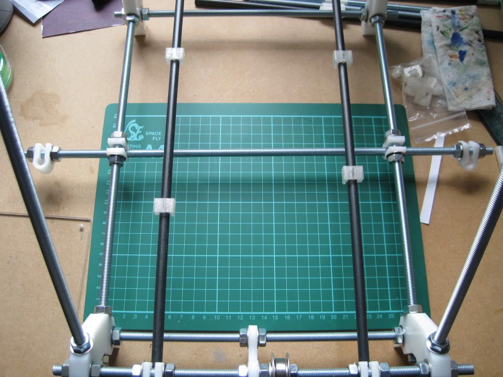
Being a bit of a perfectionist, I wanted the lower plate to be completely square and centered on the bushings. Any error here will be apparent, due to the clear nature of the acrylic. I spaced the bushings with a tape measure, and used my cutting mat below to make sure they were level.


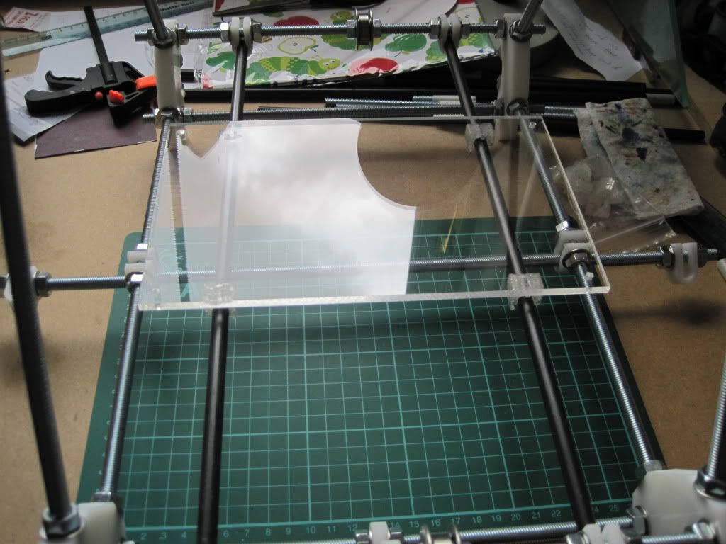
I used superglue to stick the plate to the bushings (which I hope will hold). I used the lines on the cutting mat again to ensure the plate was well aligned.


I'll check later that the glue has dried and formed a strong bond.

In other news, I ordered the bare board for the electronics this week (ebay again). This particular one is v1.1 (which has some pin assignment differences from v1.2 - I'll have to be careful in the firmware), and has the FTDI USB to serial interface chip (the single surface-mount component) already fitted. This will not only save some time and difficulty, but now I don't have to source the chip separately. it was posted at the tail end of last week, and so should be here monday or tuesday.

Up next: Probably the joys of buying even more stuff.