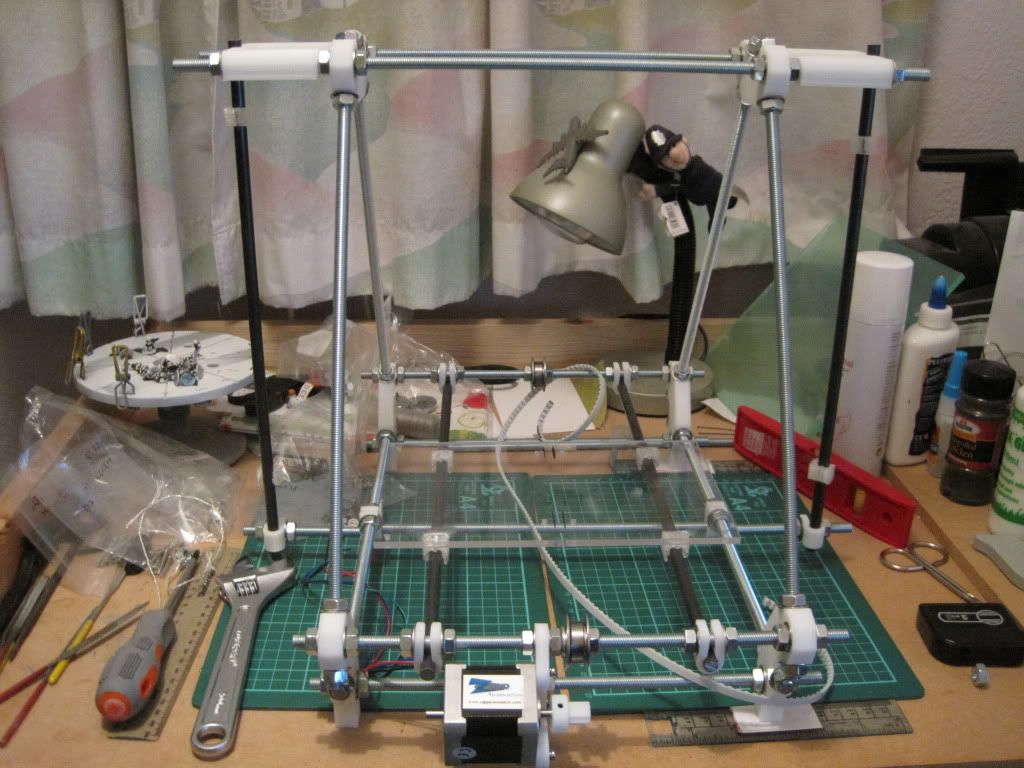
Showing posts with label build bed. Show all posts

Sunday, 15 April 2012

Chapter 26 - In which I start to actually print things

First off, my apologies for being late with the updates again - it's becoming quite a habit. I've made a fair bit of progress over the last 3 or 4 months, and I'll try and cover it all in a couple of posts.

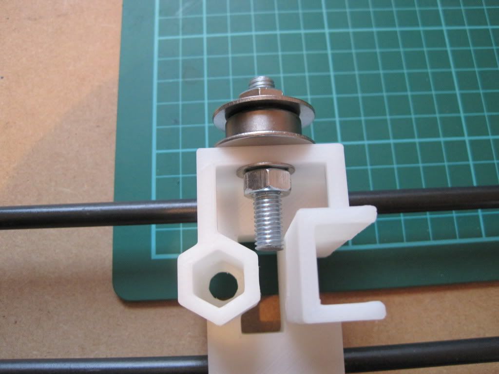
When I last posted, the printer had just printed its first proper part, and as a reward had gone on holiday to the garage over Christmas. Whilst in the garage, I decided to tackle one of those issues that had bugged me from the moment I installed the bed. Here's what I'm talking about:
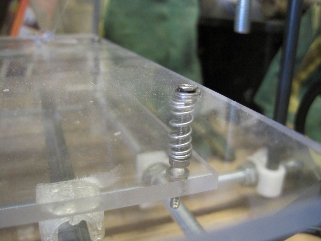

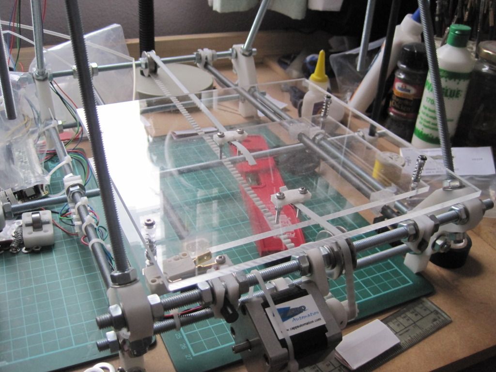
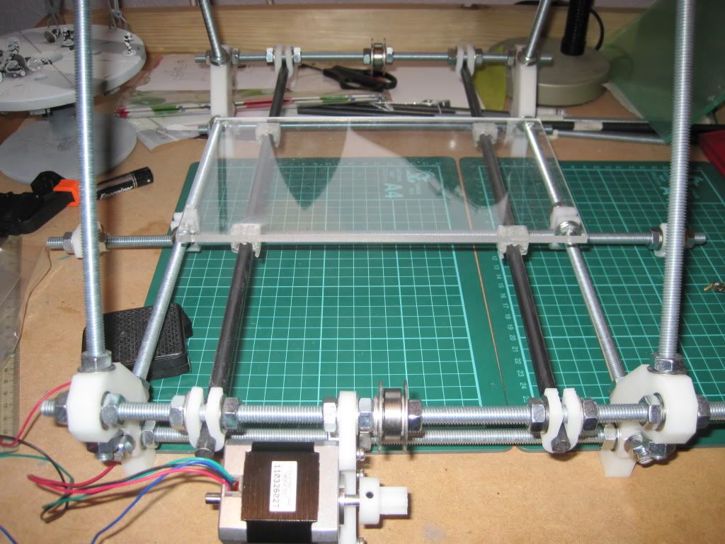
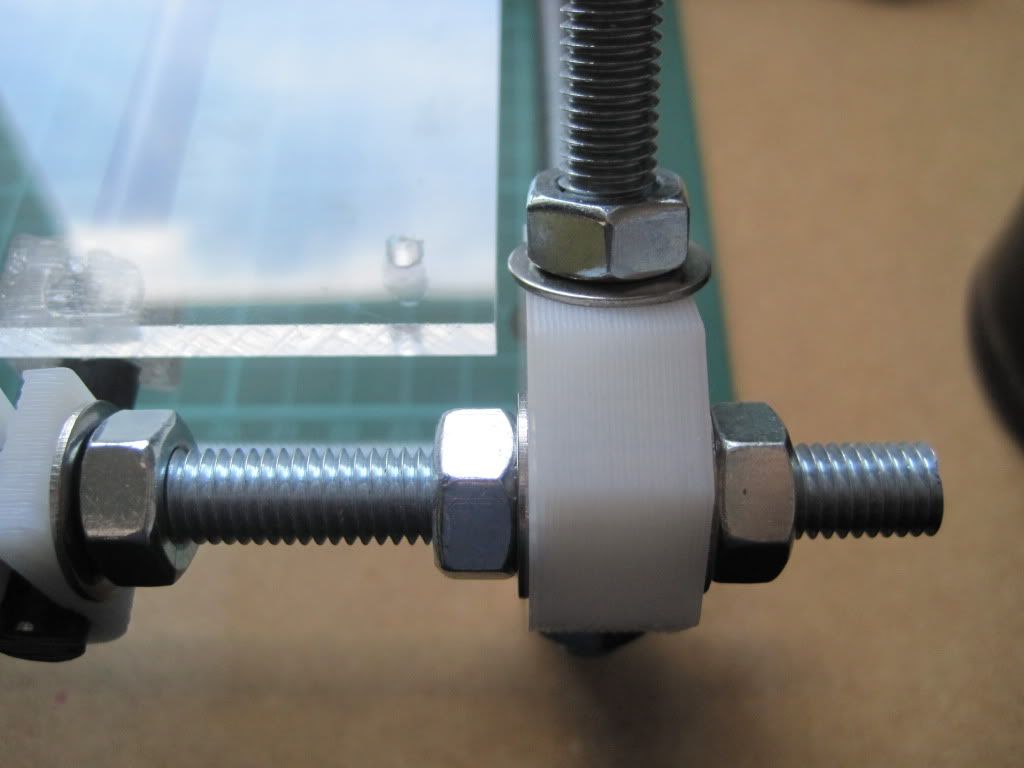
The heads of the screws that hold the bed in place stand proud of the bed surface. Sticking up like this annoyed me, as I couldn't use the maximum size of the printbed, but also because they represent a threat of collision with the head - something I only discovered by doing it!

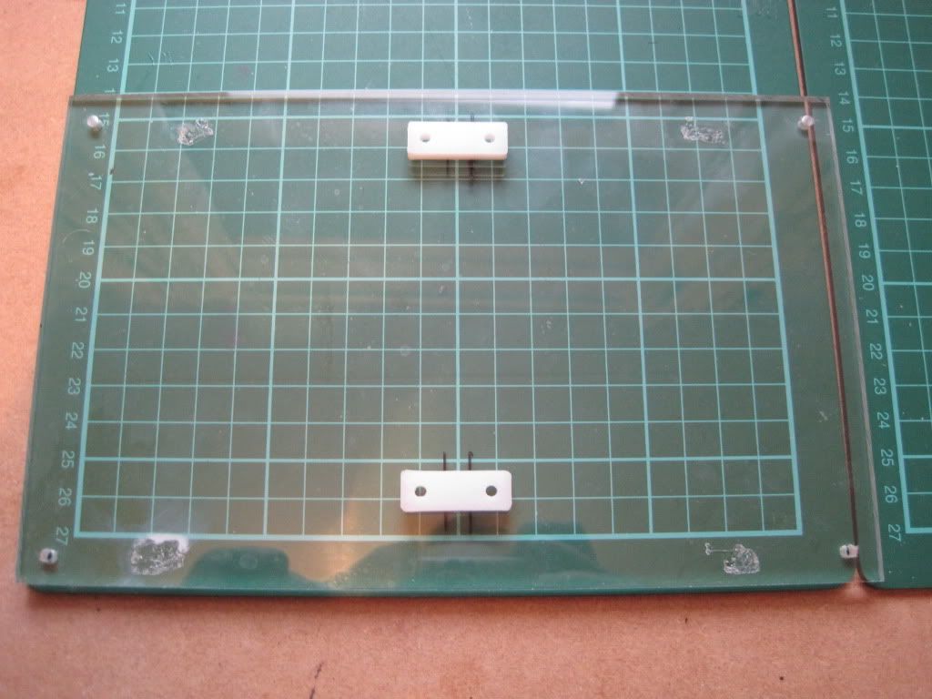
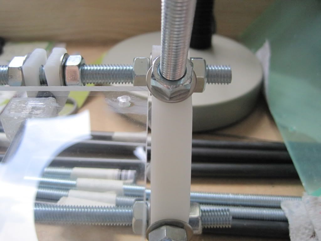
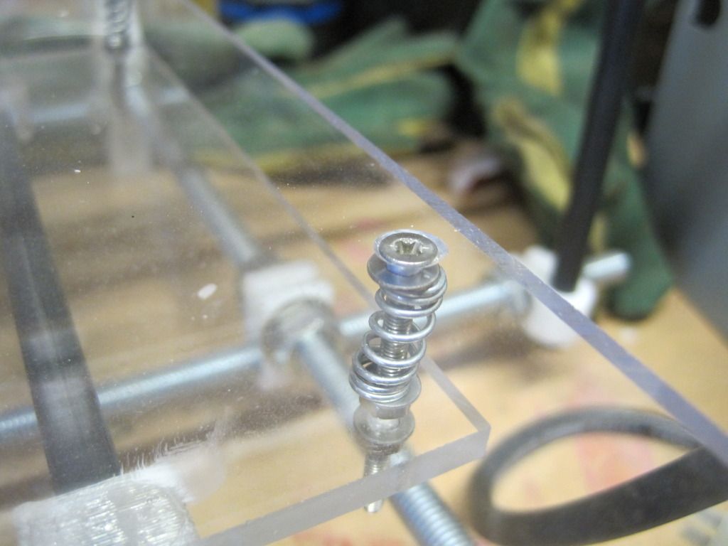
I removed the printbed and used a hand countersinking tool to recess the screw heads:


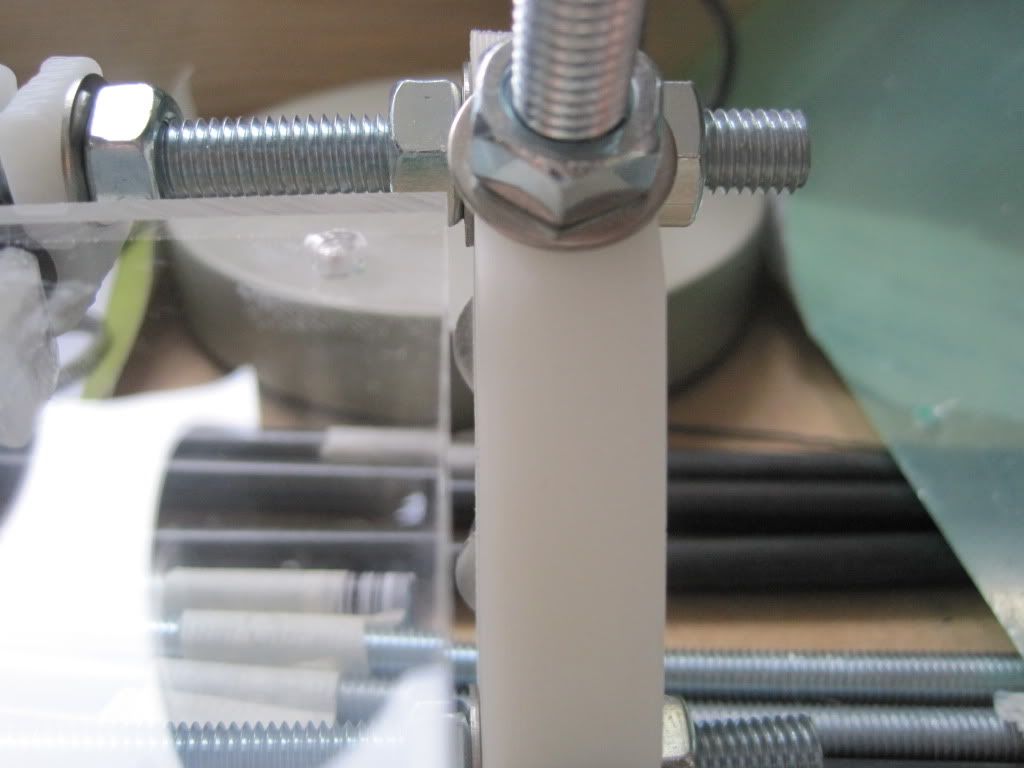
That's much better:

This was all in the middle of January. Jump forward to mid February, and the printer is back on my workbench and I'm starting to iterate towards some decent print settings. I've started using the most awesome slic3r as my gcode generator, as it is simple to set up and seems to produce good prints. If you haven't tried it yet, it's well worth it. It seems as if the strangely shaped cube in my last post was a result of skeinforge - I don't know what happened, but slic3r is giving good prints so I' gonna stick with it.

The following photo shows some of the cubes I printed to start getting the settings correct. As you can see, they start off awful on the left, and get better as I reduced the layer height and nozzle size in slic3r. I also changed the size of the cube from 20x20x20 to 20x20x10 and then 20x20x5 as it was possible to tell how good the settings were without needing to take the time of building the full height.
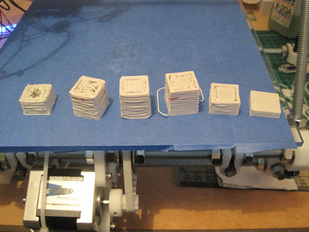

The settings that I have settled on (for now) are: Layer height of 0.3mm, perimeter speed of 30mm/s, a temperature of 220C and a bottom layer height ratio of 0.7. I'll include a full slic3r config file at the bottom of this post with the complete settings in, for anyone who is interested (or would like a starting point). This resulted in the final cube on the right, which looks like this close up:
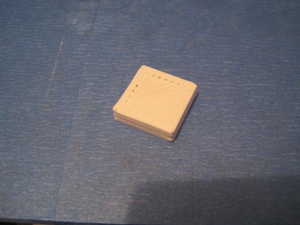
This cube was printed with a nozzle size of 0.45, which is a bit big still hence the poor fill on the top layer


Tuning of the first layer height ratio took a long time, and seemed inconsistent (and I know why now - will come to that in a later post). This photo shows the consequences:
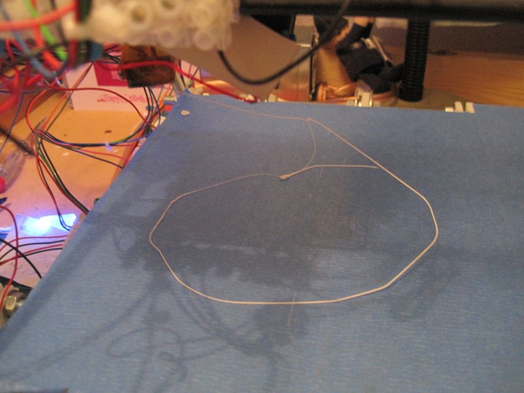

The first layer was too high, and came unstuck - the was the skirt, before the first layer of the object went down!

At this point, my feedstock (3mm "Architects Stone" PLA from Faberdashery) was being stored in the box it came in, on the floor, and being unrolled by hand as I was printing. It looked as if there was some tension on the feedstock and consequently on the X-carriage. I decided a filament spool was the first upgrade I ought to print, and so went off to thingiverse and downloaded http://www.thingiverse.com/thing:8317 and http://www.thingiverse.com/thing:10254.

I figured I'd try to print the arms of the spool holder first. In the immortal words of the Top Gear team, how hard could it be?

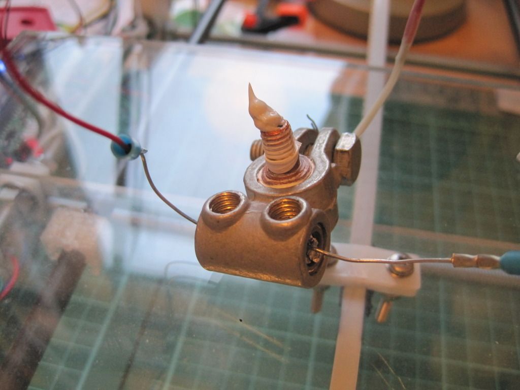
Pretty hard, as it turns out. Not only did I have to contend with varying height ratios for which there was no cure (I must have levelled the bed 3 or 4 times, grrr!) but also I had not 1 but 2 cabling breaks, right here at the main terminal block on the carriage:
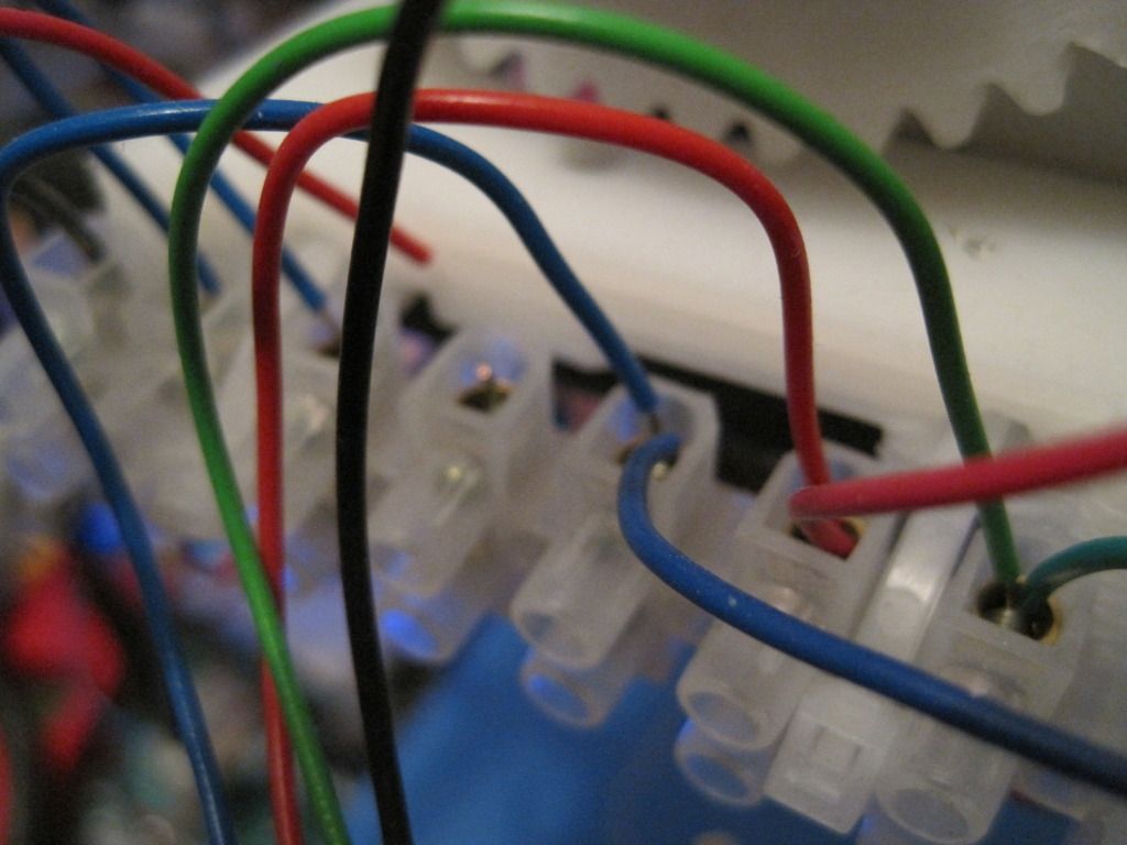

The heater power wire had broken! The printer is wired with single-core cable, and it broke here as there is no strain relief. I've added some loops of cable to all the wiring now, to try and prevent this from happening again. I also had a thermistor wire break, at the same place. Thankfully this caused the printer to fail safe, with either pronterface or the firmware switching the heater off.

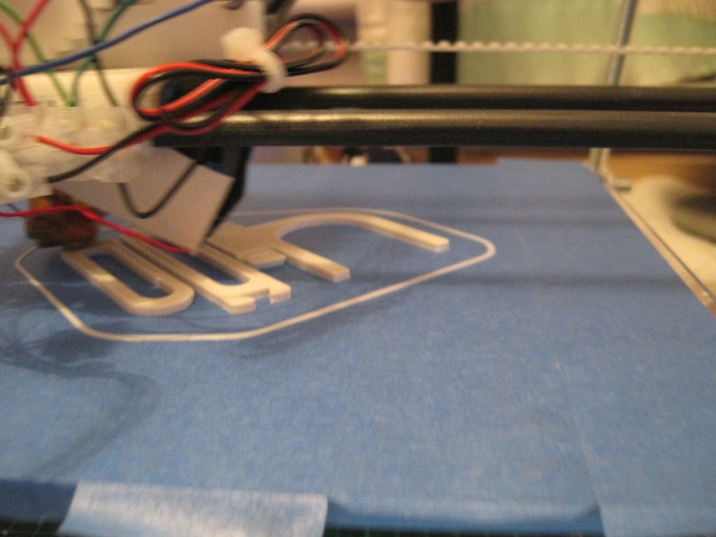
Here is a rather poor photo of an arm in progress:

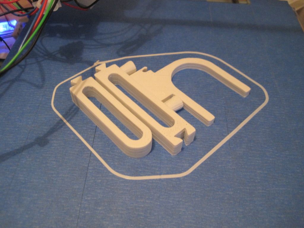
Finally I got my first parts off the machine - the feeling of having actually made something is fantastic!

So, up next - more parts for the spool holder, more problems and more resolutions!

Example slic3r config, as used in april 2012:

bottom_layer_speed_ratio = 0.2
bridge_flow_ratio = 1
bridge_speed = 60
duplicate_distance = 6
duplicate_x = 1
duplicate_y = 1
end_gcode = M104 S0 ; turn off temperature\nG28 X0  ; home X axis\nG28 Y0 ; home y axis\nM84     ; disable motors
extrusion_axis = E
extrusion_multiplier = 1
extrusion_width_ratio = 0
filament_diameter = 2.86
fill_angle = 45
fill_density = 0.5
fill_pattern = rectilinear
first_layer_height_ratio = 0.7
g0 = 0
gcode_arcs = 0
gcode_comments = 0
infill_every_layers = 1
infill_speed = 40
layer_height = 0.3
nozzle_diameter = 0.4
output_filename_format = [input_filename_base].gcode
perimeter_speed = 30
perimeters = 2
print_center = 100,100
retract_before_travel = 0.5
retract_length = 3
retract_lift = 0
retract_restart_extra = 0
retract_speed = 30
rotate = 0
scale = 1
skirt_distance = 12
skirt_height = 1
skirts = 2
small_perimeter_speed = 30
solid_fill_pattern = rectilinear
solid_infill_speed = 30
solid_layers = 3
start_gcode = G28 ; home all axes\nG92 E0 ;reset extruder\nG1 E3 F1200 ;Prime extruder 3mm\n;G1 E2 F1200 ;retract extruder 1mm\nG92 E0 ;reset extruder
temperature = 220
travel_speed = 130
use_relative_e_distances = 0
z_offset = 0
Sunday, 18 December 2011

Chapter 23 - In which I describe a catalogue of failures

Apologies for still being behind with the blog. Have been a bit busy recently, and as usual the "write-up" suffers.

I had fitted up the hotend, wired everything up and was good to go. I fired up Bernard, opened pronterface and set the temperature to 185 (the pronterface default for PLA). I loaded some feedstock into the extruder (not easy with all those springs) and ran it forwards until it was down in the barrel. I waited for the hotend to come up to temperature - this took a while, but I was expecting that as the mass of this hot end is fairly large.

Once at temperature, I tried to extrude. The result: a little dribble of filament, and nothing more. I tried again and this time was rewarded with the following:


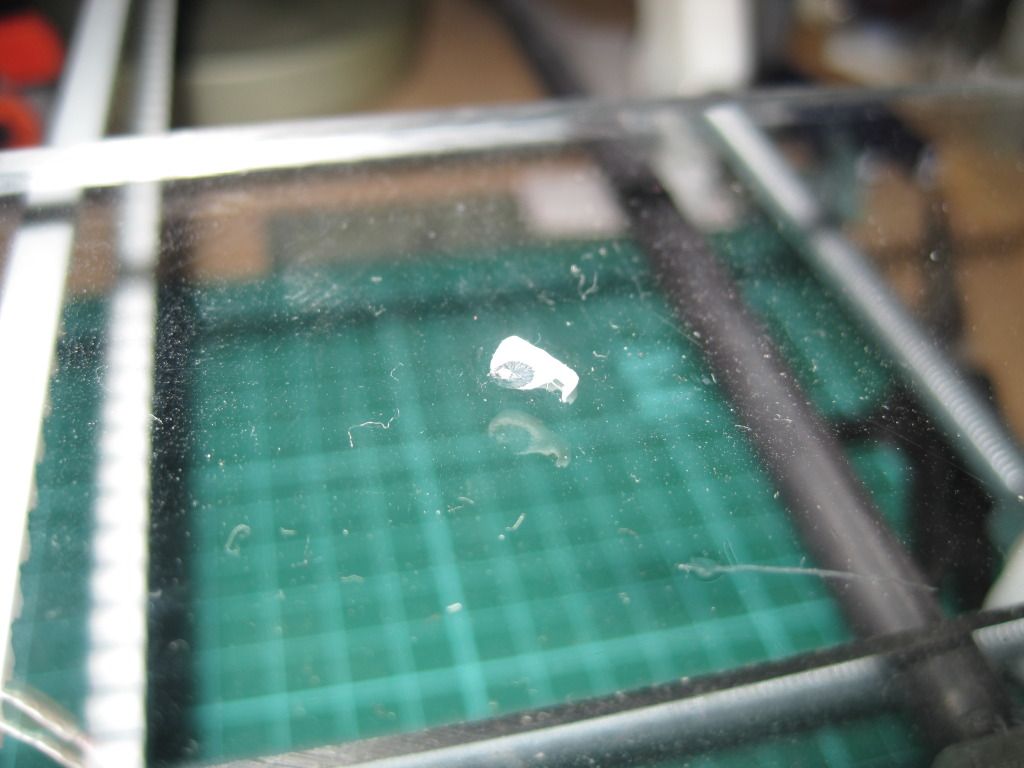
The PTFE had failed, and dropped the hotend, still at temperature, onto the bed. To be fair, I was expecting this to happen (apparently it always does) but had expected more printing time from it! I lifted the Z axis - this would let the hotend hang in mid air to cool down. It left this smear of PLA bonded to the acrylic:


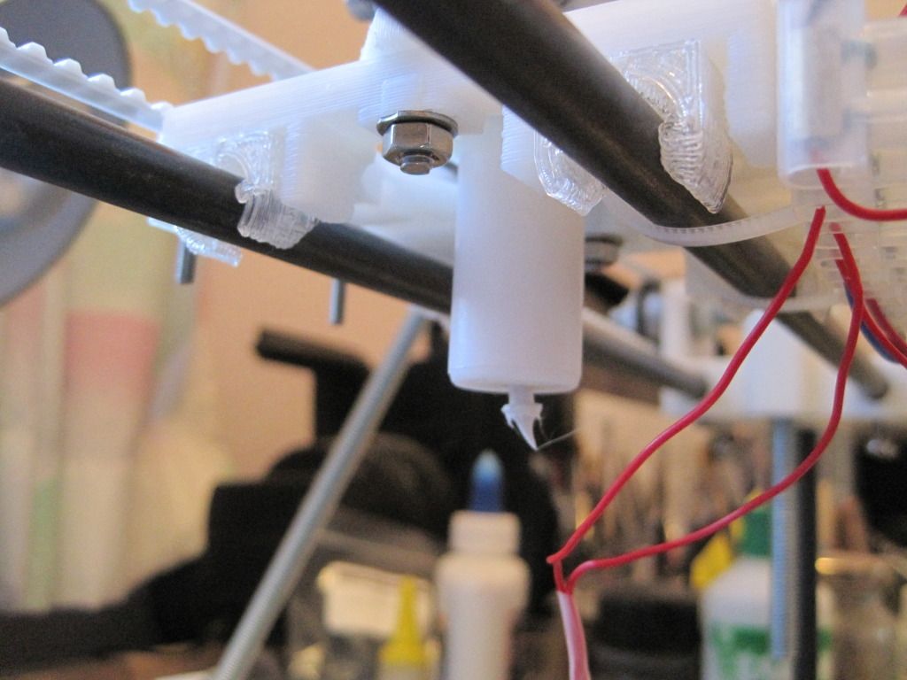
Here is the end of the feedstock:


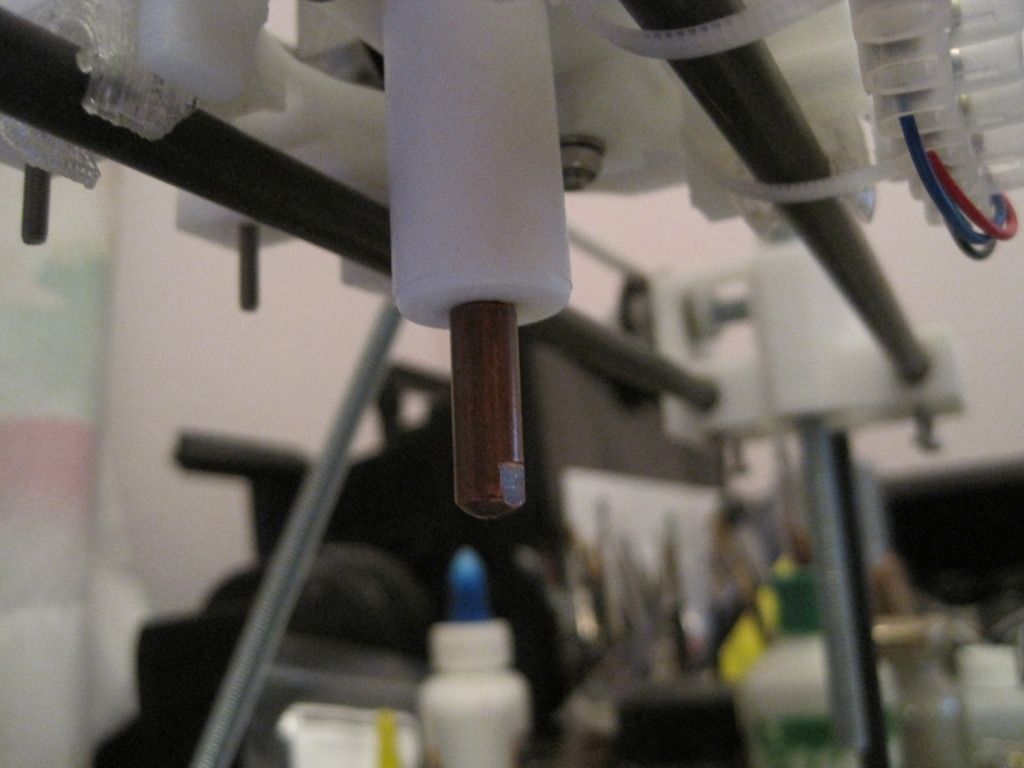
Looks like the PLA may have expanded into a gap, and the resulting pressure forced the nozzle out of the PTFE. Interestingly another MIG tip screwed into the barrel ok, although it was a little loose at the start:


I put everything back together, optimistically hoping it would hold up OK. It didn't and rapidly failed again in the same way, which is fairly obvious now.

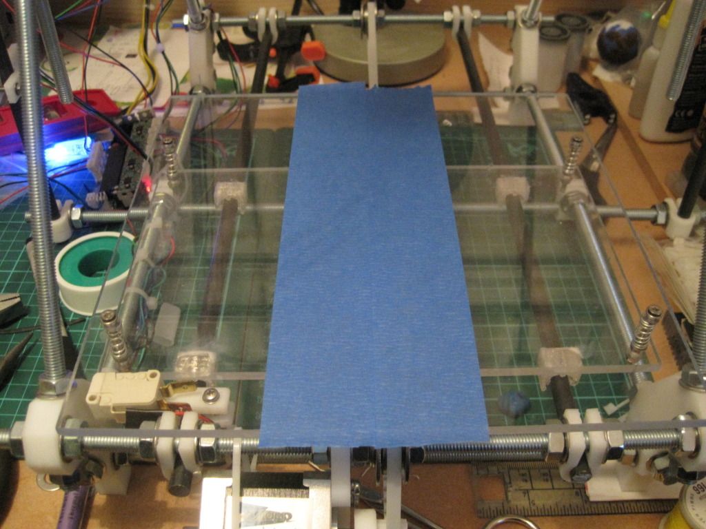
I took the extruder apart, and replaced the PTFE with one of the failed ones from before, that I had re-tapped to M6. This had a straight-through bore of 5mm. In anticipation of actually printing something,  I added some blue tape to the printbed:


I realise now that it was pretty silly to use a large bore PTFE barrier, but I had been reading Nopheads thoughts on tapered expansion zones, and wondered if the same effect could be achieved with the larger bore.

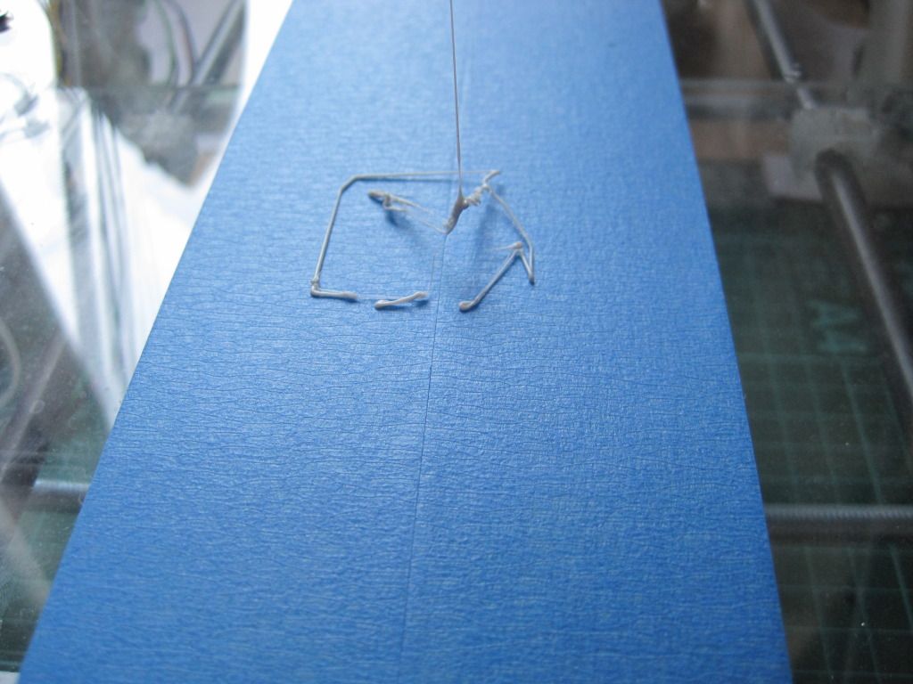
Things actually looked pretty good for a few moments once it was up to temperature. It extruded filmant ok, and so I loaded up the STL for a 20mm cube and pressed the "print" button - a scary moment! I got the following, before another failure:


Predicatbly it failed again. what was interesting though was the feedstock in the barrel - instead of buckling, it had curled up as it warmed up and was pushed downwards, leading to a melt zone that was seemingly viable, albeit for a short period of time.

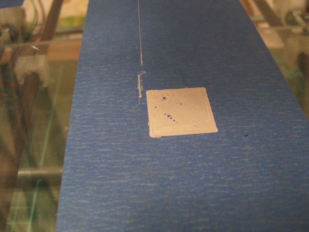
I repaired it again, with another for the failed barrels, and managed to get the following before the next failure:


Its square and kinda filled in - almost a success! It is only one and a half full layers, and the infill looks off, but that's to tweak another day.

Spurred on by this success, I went back to the garage and drilled and tapped the opposite end of one of the failed barriers. I drilled this one to 4.8mm (less than the recommended tapping size of 5mm) to try and get deeper threads, and I only tapped three quarters of the thread -  I used a mig tip to thread-form the rest, such that it matched the thread exactly.

Surely this ultimate barrier wouldn't fail?

You'll have to wait till next time to find out, as I haven't downloaded the pictures yet!

Sunday, 16 October 2011

Chapter 20 - In which problems are rectified, and I make a temperature sensor the professional way
Its been a while since my last post. This is due to having had a week away in Scotland, but also due to progress being slow. I have however made some progress.

Firstly I changed the angle of the X-axis endstop. I had test-fitted the extruder body, and found the endstop was in the way. There is a conveniently provided little square protrusion on the side of the carriage, and the contact of the realigned endstop sits nicely on it.

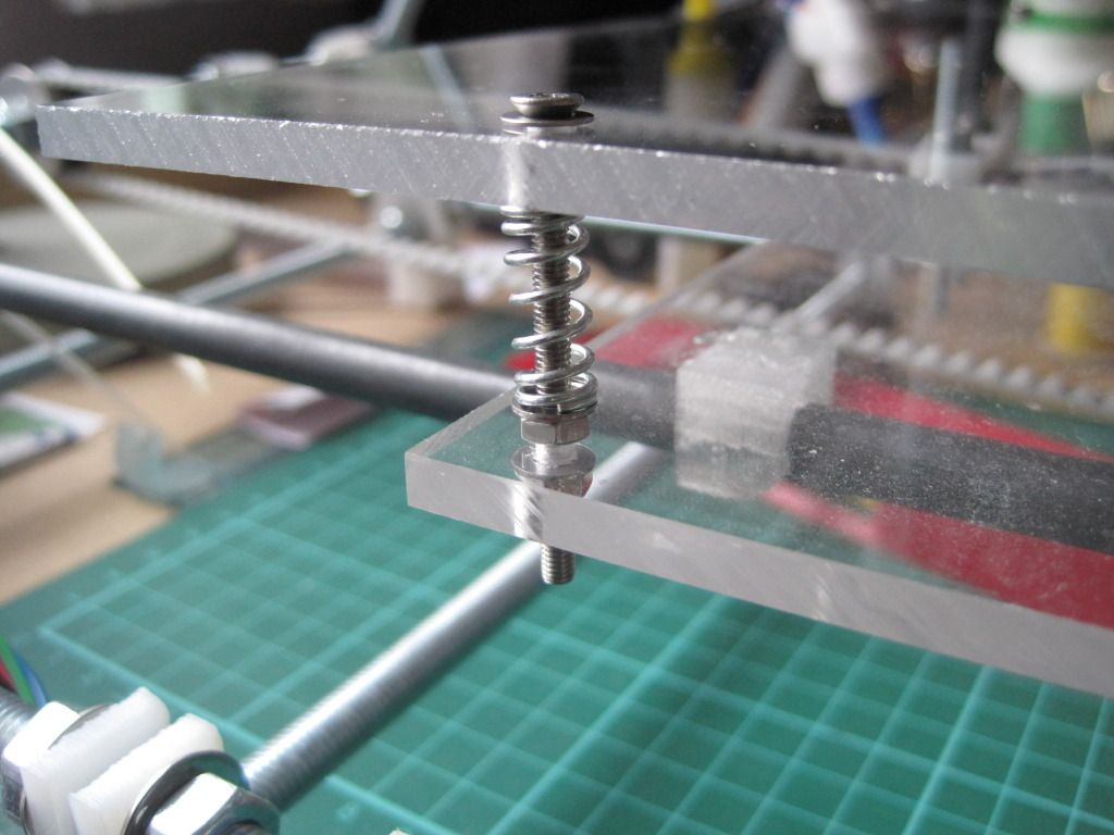
I then proceeded to fit the print bed. I had spotted this post on the forum, and decided to make the upgrade now rather than later. I had also got lots of peg springs just waiting for a use. I have used countersunk screws to mount the bed, but only because they were the only ones I could get with the correct length. There are washers under the heads to prevent the screws pulling into the bed and cracking it.


The bed is fairly level as it is, but I may tighten up the nuts to compress the springs, making the bed firmer and less prone to wobble. This has the added advantage of giving some extra Z height.


I had ordered some replacement bolts to hobb, as the previous one was too narrow. Once they turned up, I spent an evening in the garage attempting to hobb one of them. It was much harder going than the previous bolt - maybe these are made of something harder? I was also trying to hobb with an M6 tap as opposed to an M3, to give bigger teeth on the bolt. I just couldn't get it to cut the teeth correctly, and it left an un-cut section in the middle of the bolt. I ended up getting very frustrated with it, and walked away trying to decide how to go about making one properly.

I came back to it a week or so later, and had a proper look in the daylight. The hobbing down one side looked pretty good, and fairly even. I figured that I could probably space the bolt such that the good section was doing the driving.


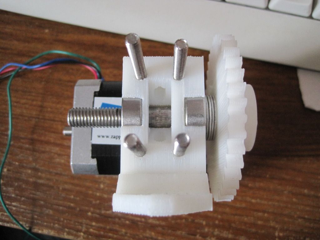
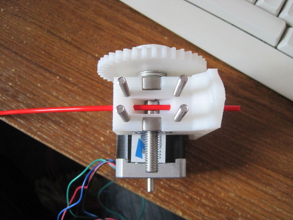
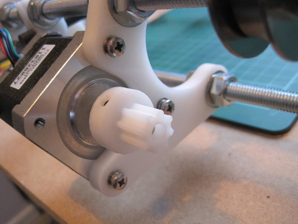
I put the extruder back together, and was pleasantly surprised to find that the good section was in the correct place already. Better than that, it had enough grip to drive feedstock without the idler in place! Whilst working on the extruder, I also moved the motor and fitted the bolts that will mount the extruder to the X-carriage. I reassembled the extruder and idler, and repositioned the motor to get the best interface between the gears.


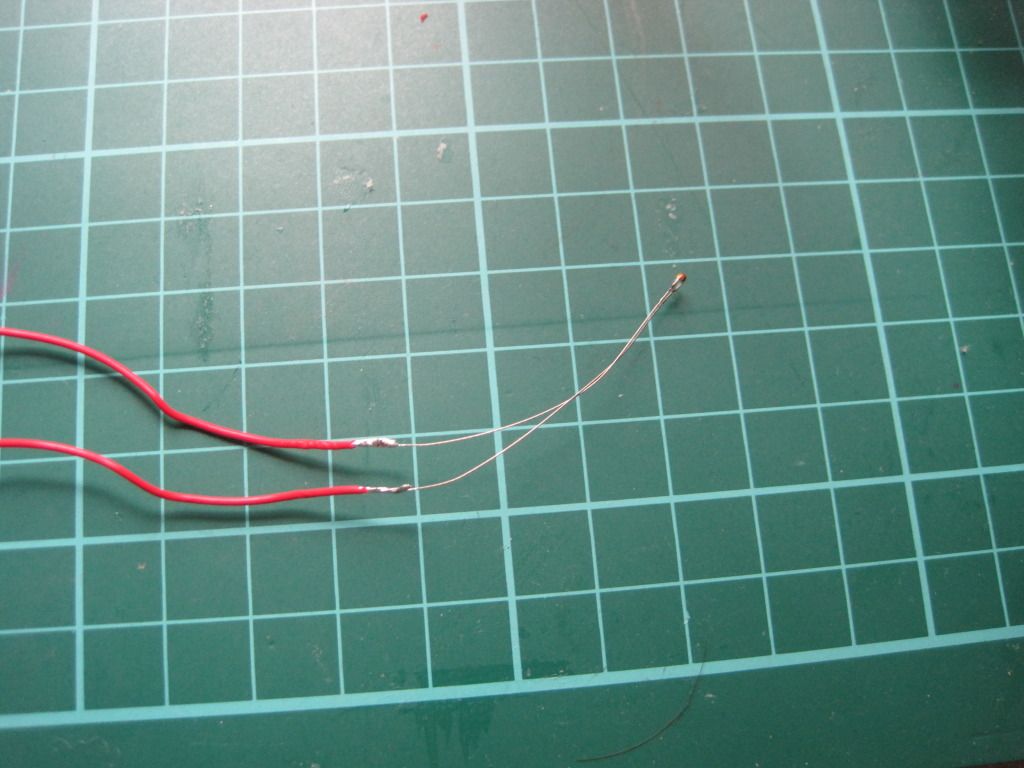
I also had the time to make up the hot-end temperature sensor. I constructed this in a similar manner to how professional temperature sensors are made. Firstly I soldered the ends to the stripped ends of the PTFE wire:


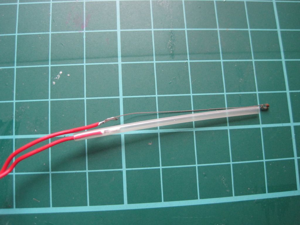
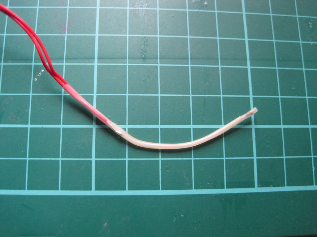
I then used high-temperature heat-shrink sleeving to insulate one leg, all the way from the small joint at the thermistor head to past the solder join:


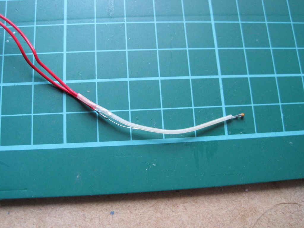
I shrunk the sleeving with the kind help of my girlfriend and her crafting hot air gun:


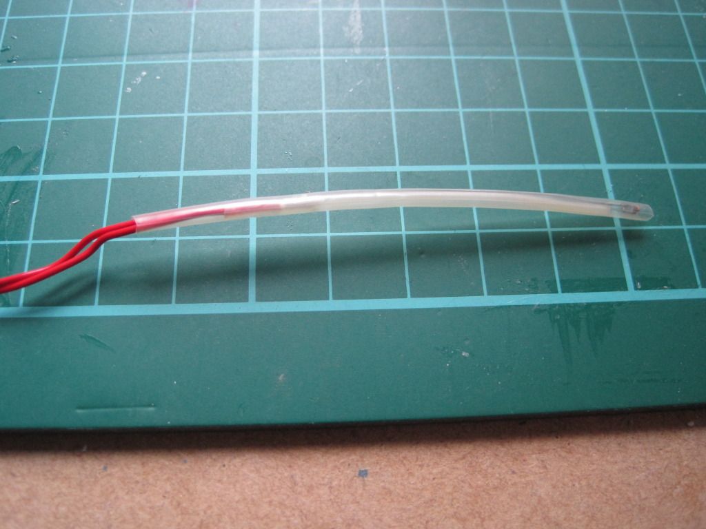
I then used a larger diameter piece of the same sleeving to cover the entire assembly, from a point past the thermistor head to past the remaining soldered joint.


Lastly I trimmed the overhanging sleeving close to the bead. This assembly method should provide a robust and short circuit-free sensor for the hot end.

And Thats all the I've managed to achieve. Next up: The long-awaited hot-end post?

Thursday, 18 August 2011

Chapter 10 - In which I cheat a little, and things get back on track

Things are starting to look up - I now have all of the parts I need to finish my reprap, with the exception of some hot end bits (I think). The major cause of the delay was bought on by myself. In a bid to reduce the cost and number of surplus fixings I'd be left with, I opted to purchase the majority of the components I need through the company I work for. We use a vast array of fixings and electronic components, and I was able to get hold of almost everything I needed. Placing the order, and picking all the parts too longer than expected, but now it is all done I can crack on with the build.

Here are the majority of the parts I purchased:

Mechanical parts
Electronics
The microswitches in the first picture have 90 degree arms on them, and will need to be modified before use as endstops. They were more expensive than most of the others I looked at on the web, but they are good parts. They're UL and CSA approved, and are rated to switch 15 Amps. Whilst I'll never need that much, it provides a margin for error, especially if I end up with a firmware that doesn't use the processor's internal resistors. Speaking of processors, I purchased that too but haven't got a photo yet.

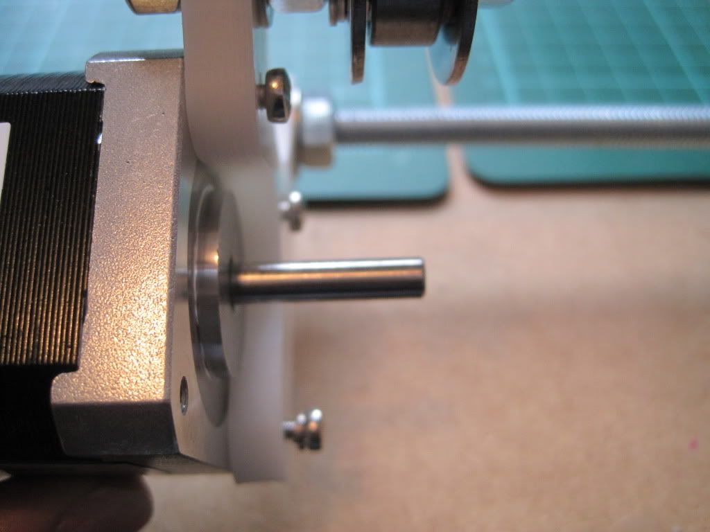
I got back to work by attaching the Y axis stepper motor. We don't carry M3 by 10mm screws at work, so I got 12mm long ones instead. I knew that the motor screw holes bottom out and that 12mm would be too long, so I got some spring washers to take up the slack.

The screws fully seated - you can see the slack caused by them being too long. The bottom screw has the spring washer fitted.

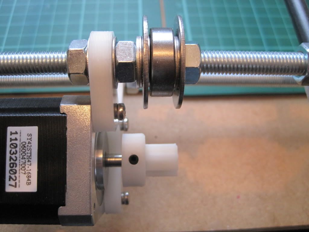
Next I fitted the pulley to the motor shaft. I had gotten a couple of pointy grub screws, thinking that flat ended ones wouldn't grip the shaft well, but hadn't looked at the screws Nophead had supplied. These turned out to be pointed as well, so I kept them (thanks Nophead!). I aligned the pulley with the bearing and tightened it into the shaft before checking that it gripped well and didn't turn. At the same tie, I moved the Y axis bearings closer to the middle of the frame. They were a way off to one side, and I was worried about off-centre forces affecting the movement of the axis. I brought them as close to the centre as possible.


I realised I had forgotten the plain washers behind the spring washers. I went back and fitted them.

I wrapped the Y axis belt (the shorter of the 2 supplied) around the bearings and lined it up over the lower sheet. I marked where it lay on the sheet, and started to carefully remove the sheet form the Y axis smooth rods. Then, disaster! - the bushings came off. Whilst the superglue had done a good job of holding it while it was flat, it cracked when I started to move it vertically.


I took the sheet off completely and used the opportunity to mark up the clamp holes and drill them.


I glued the lower tray down to the bushings again, and will continue with the fitting and tensioning of the belt when the glue is dry. The only good thing to come of this is that the movement seems a little smoother now I've reglued it. Perhaps the bushings were misaligned when I fitted them initially.

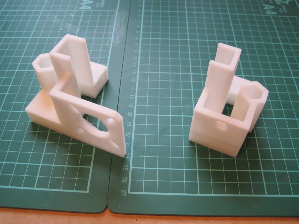
Whilst waiting for the glue to dry, I figured I'd make a start on the X axis. Here are the ends:


The holes are all the right size, so no need to drill anything out. I fitted the nuts into the traps, which was a little fiddly. I used the end of a file to make them lie flat when needed:


I fitted M3x12 screws into the nuts (again lacking in 10s). These seem excessive (although they may have something important to do later), and I think that M3x8 or even 6 would be better.


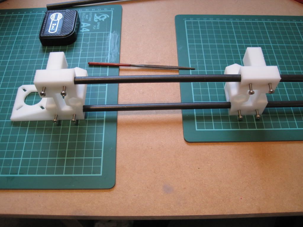
The visual instructions say to lay the parts out 500mm apart, but for the suggested X axis smooth rod length of 420mm this was too far:


Anyhow, I fitted the X ends to the rods, and tightened the screws:


I built the X end idler bearing onto a 50mm piece of threaded rod, and fitted it, and that's the X axis done for now:


The next job is to level the printer. Mine was a bit wonky:


A pair of plastic rules provided the bulk of the adjustment required, with folded post-it notes providing the fine-tuning.


After adjustment - nice and level.

I have a snap-on adjustable foot in mind as one of my first upgrades....

The preliminary adjustment of the Z rod fixings went well, and I moved on to the upper fixings. I fitted up M3x25 screws as suggested in the assembly instructions, but found they were too long. I hadn't read far enough ahead to spot the note about this! I was on the brink of turning the screws around and trying them in reverse, when I looked back at my parts list. I realised I had gotten the correct amount of 20mm screws, so I replaced the 25s and the rod restraints now fit well:

I test fitted a motor to make sure the screw threads didn't protrude too far - they don't.
The last part of this evening was spent fitting the z rods and checking them for verticality. It was a slightly painstaking process, but well worth taking time over.


So here is the machine after all of today's exertions. I'll let the glue dry overnight, and hopefully tomorrow will see the mounting of the X axis.


Next up: X's, Z's and leadscrews!

Sunday, 17 July 2011

Chapter 7 - In which I find a problem

It seems like the superglue is holding, but I haven't tried to remove the bottom plate from the axis yet - I figured I'd give the glue some more time. What I did do however was slide the plate up and down the axis. Primarily this was to check the bushings ran smoothly, but it showed up something else interesting.

This is the right hand corner of the carriage at the front of it's travel:


This is the back right hand side of the carriage at the far end of it's travel. Note the spacing of the plate from the vertex:


The Y axis is misaligned. I had measured and checked and rechecked the spacing of the smooth rods on the rear rod, but apparently not well enough. Although not a big misalignment (somewhere in the order of 0.5 to 0.75mm), it is certainly noticeable when moving the carriage.

I adjusted both the smooth rods on the rear rod by the same amount, to keep them parallel. This is the rear right hand corner after adjustment:


Much better. This step of checking the alignment is definitely worth it.