Showing posts with label wiring. Show all posts

Sunday, 15 April 2012

Chapter 26 - In which I start to actually print things

First off, my apologies for being late with the updates again - it's becoming quite a habit. I've made a fair bit of progress over the last 3 or 4 months, and I'll try and cover it all in a couple of posts.

When I last posted, the printer had just printed its first proper part, and as a reward had gone on holiday to the garage over Christmas. Whilst in the garage, I decided to tackle one of those issues that had bugged me from the moment I installed the bed. Here's what I'm talking about:
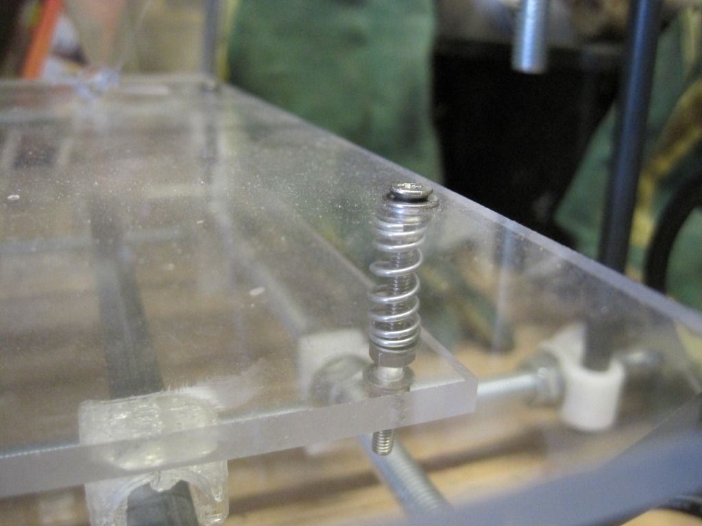

The heads of the screws that hold the bed in place stand proud of the bed surface. Sticking up like this annoyed me, as I couldn't use the maximum size of the printbed, but also because they represent a threat of collision with the head - something I only discovered by doing it!

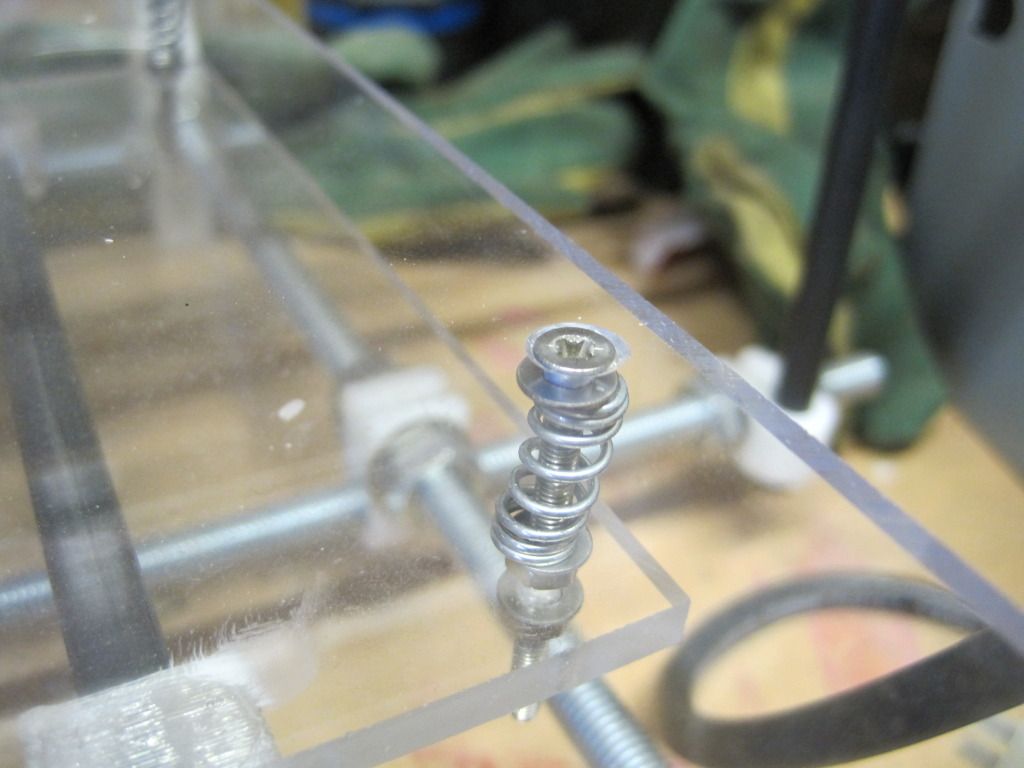
I removed the printbed and used a hand countersinking tool to recess the screw heads:


That's much better:

This was all in the middle of January. Jump forward to mid February, and the printer is back on my workbench and I'm starting to iterate towards some decent print settings. I've started using the most awesome slic3r as my gcode generator, as it is simple to set up and seems to produce good prints. If you haven't tried it yet, it's well worth it. It seems as if the strangely shaped cube in my last post was a result of skeinforge - I don't know what happened, but slic3r is giving good prints so I' gonna stick with it.

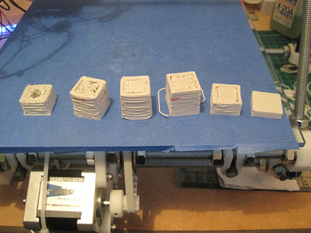
The following photo shows some of the cubes I printed to start getting the settings correct. As you can see, they start off awful on the left, and get better as I reduced the layer height and nozzle size in slic3r. I also changed the size of the cube from 20x20x20 to 20x20x10 and then 20x20x5 as it was possible to tell how good the settings were without needing to take the time of building the full height.

The settings that I have settled on (for now) are: Layer height of 0.3mm, perimeter speed of 30mm/s, a temperature of 220C and a bottom layer height ratio of 0.7. I'll include a full slic3r config file at the bottom of this post with the complete settings in, for anyone who is interested (or would like a starting point). This resulted in the final cube on the right, which looks like this close up:
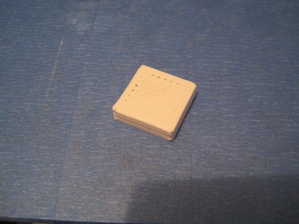
This cube was printed with a nozzle size of 0.45, which is a bit big still hence the poor fill on the top layer


Tuning of the first layer height ratio took a long time, and seemed inconsistent (and I know why now - will come to that in a later post). This photo shows the consequences:
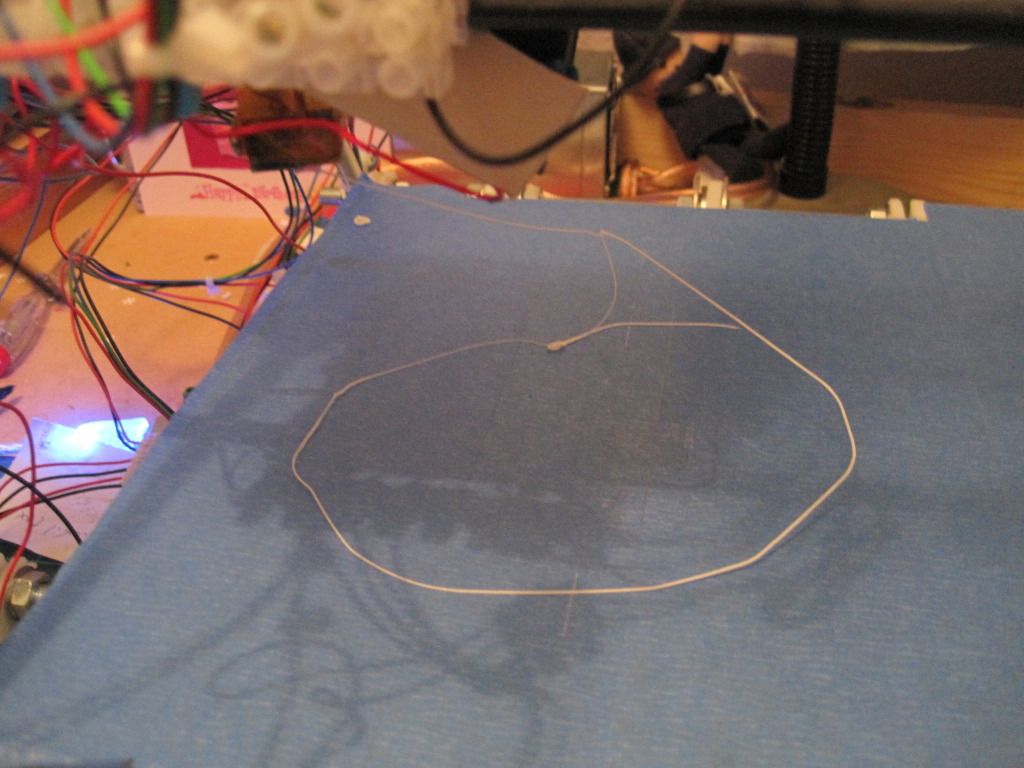

The first layer was too high, and came unstuck - the was the skirt, before the first layer of the object went down!

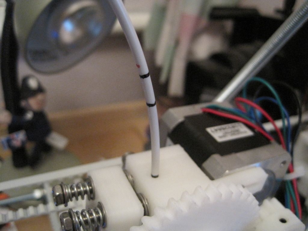
At this point, my feedstock (3mm "Architects Stone" PLA from Faberdashery) was being stored in the box it came in, on the floor, and being unrolled by hand as I was printing. It looked as if there was some tension on the feedstock and consequently on the X-carriage. I decided a filament spool was the first upgrade I ought to print, and so went off to thingiverse and downloaded http://www.thingiverse.com/thing:8317 and http://www.thingiverse.com/thing:10254.

I figured I'd try to print the arms of the spool holder first. In the immortal words of the Top Gear team, how hard could it be?

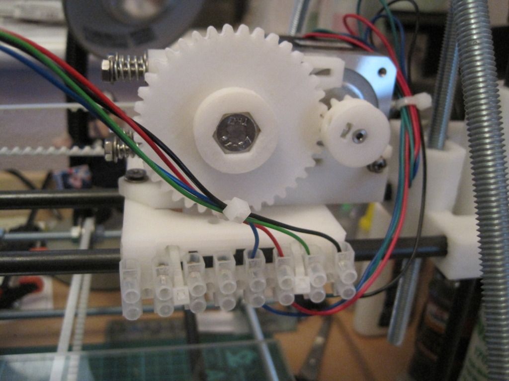
Pretty hard, as it turns out. Not only did I have to contend with varying height ratios for which there was no cure (I must have levelled the bed 3 or 4 times, grrr!) but also I had not 1 but 2 cabling breaks, right here at the main terminal block on the carriage:
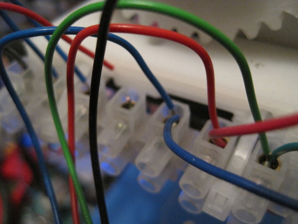

The heater power wire had broken! The printer is wired with single-core cable, and it broke here as there is no strain relief. I've added some loops of cable to all the wiring now, to try and prevent this from happening again. I also had a thermistor wire break, at the same place. Thankfully this caused the printer to fail safe, with either pronterface or the firmware switching the heater off.

Here is a rather poor photo of an arm in progress:
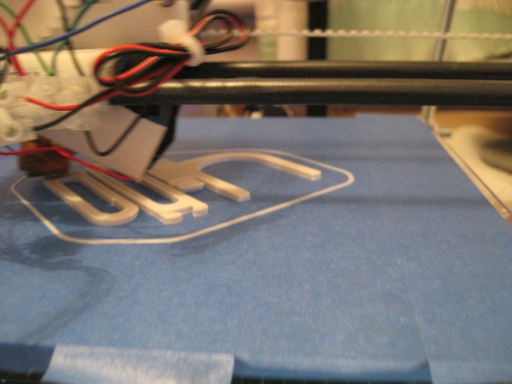

Finally I got my first parts off the machine - the feeling of having actually made something is fantastic!
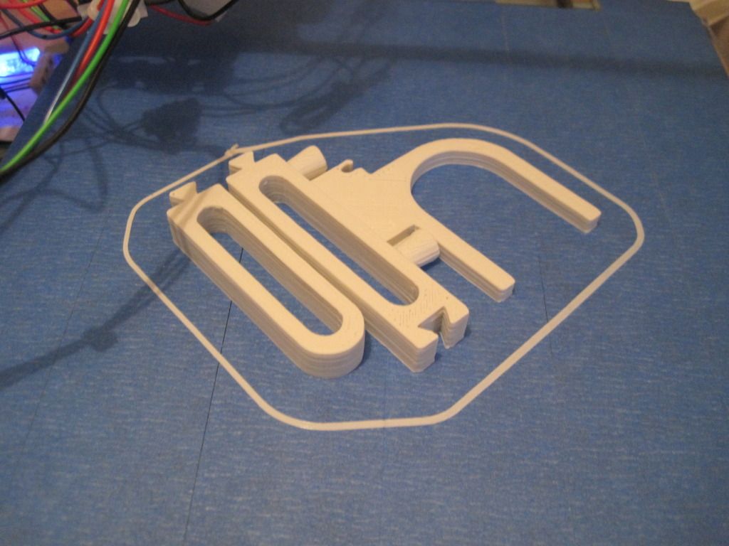

So, up next - more parts for the spool holder, more problems and more resolutions!

Example slic3r config, as used in april 2012:

bottom_layer_speed_ratio = 0.2
bridge_flow_ratio = 1
bridge_speed = 60
duplicate_distance = 6
duplicate_x = 1
duplicate_y = 1
end_gcode = M104 S0 ; turn off temperature\nG28 X0  ; home X axis\nG28 Y0 ; home y axis\nM84     ; disable motors
extrusion_axis = E
extrusion_multiplier = 1
extrusion_width_ratio = 0
filament_diameter = 2.86
fill_angle = 45
fill_density = 0.5
fill_pattern = rectilinear
first_layer_height_ratio = 0.7
g0 = 0
gcode_arcs = 0
gcode_comments = 0
infill_every_layers = 1
infill_speed = 40
layer_height = 0.3
nozzle_diameter = 0.4
output_filename_format = [input_filename_base].gcode
perimeter_speed = 30
perimeters = 2
print_center = 100,100
retract_before_travel = 0.5
retract_length = 3
retract_lift = 0
retract_restart_extra = 0
retract_speed = 30
rotate = 0
scale = 1
skirt_distance = 12
skirt_height = 1
skirts = 2
small_perimeter_speed = 30
solid_fill_pattern = rectilinear
solid_infill_speed = 30
solid_layers = 3
start_gcode = G28 ; home all axes\nG92 E0 ;reset extruder\nG1 E3 F1200 ;Prime extruder 3mm\n;G1 E2 F1200 ;retract extruder 1mm\nG92 E0 ;reset extruder
temperature = 220
travel_speed = 130
use_relative_e_distances = 0
z_offset = 0
Tuesday, 29 November 2011

Chapter 22 - In which I mount the hot-end, and find useful things in the garage

Firstly let me apologise for not posting in a while. Things have been busy here, and as usual the write-up get left until later. We resume our story just as I have built my DIY nozzle and heater block....

With the hot end assembled, it was time to mount the thermal barrier. It was a tight fit in the heater block, so I got it started by hand and then used a ratcheting clamp to squeeze it fully home.


I mounted a 2.5mm drillbit in a chuck for the electric screwdriver, and drilled and tapped the holes to hold the thermal barrier in place.


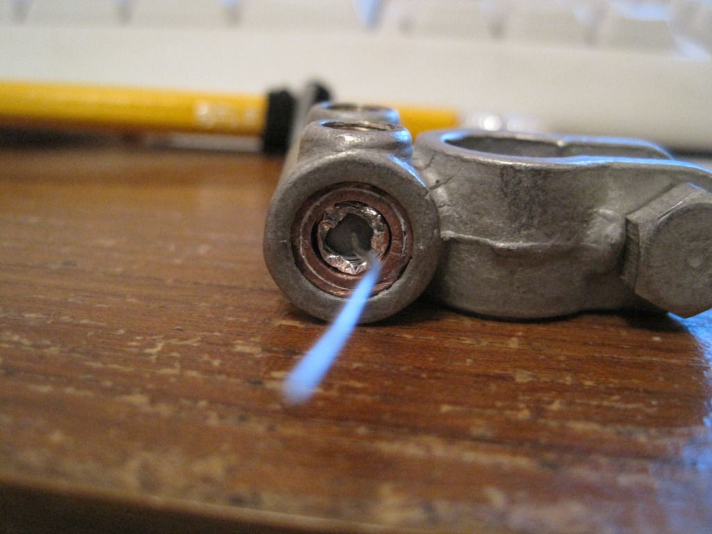
 Next I test fitted the heater resistor and its spacing sleeves into the battery clamp. As the following photo shows, there was still a gap to eliminate.


Remembering a tip from the forums, I wrapped the outer sleeve and the resistor with tin-foil, until they were a tight fit within the clamp.


Next I mounted the extruder body to the X-carriage and wired it up. I mounted a terminal block with cable ties through the fan mounting holes on the carriage.


I loaded up the feedstock and performed the E_steps_per_mm calibration for volumetric extrusion as found (prusa method: insert link here).


I performed the calibration with the hotend removed for ease. I ended up with a figure of (EDIT, May 2012:  I found my initial E steps figure during a tidy up - I worked it out to be 488.4)

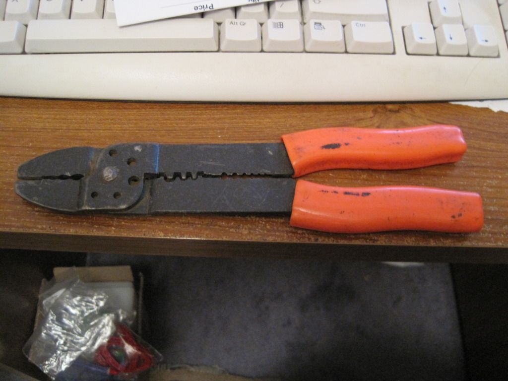
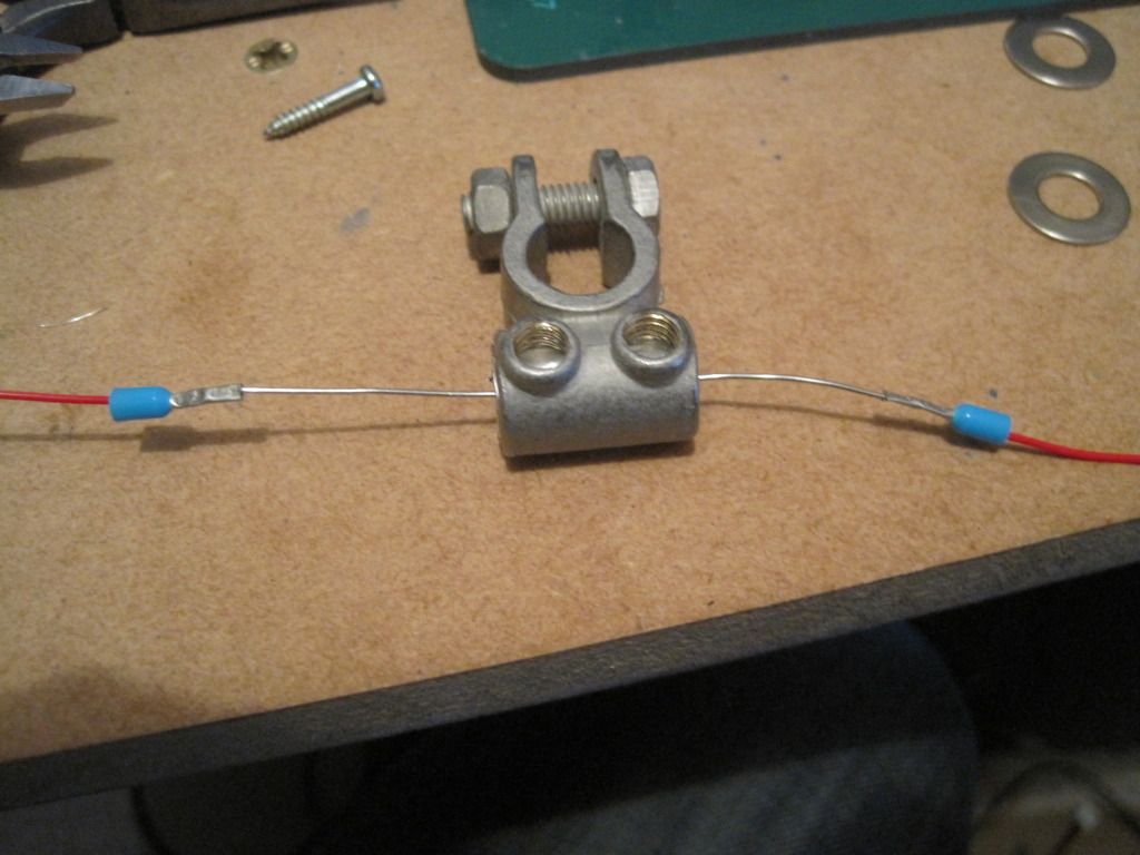
I prevoius look around my Girlfriend's Dad's garage had provided me with a crimping tool, that I used to fit some PTFE wire to the resistor legs via a pair of bootlace ferrules. Isn't it funny that sometimes the right tool turns up at the right time?


I covered the outer nozzle sleeve in a thin layer of heat sink paste, and set about clamping it into place. I had thought this to be a fairly easy task, but it turned out to be much harder than I had anticipated. The outer sleeve wasn't really big enough and so there was a very large reduction to be made by the clamp's bolt. Eventually I had to resort to a pair of pliers, as the bolt was distorting the clamp too much. With the aid of a very patient girlfriend, it was eventually tightened up.


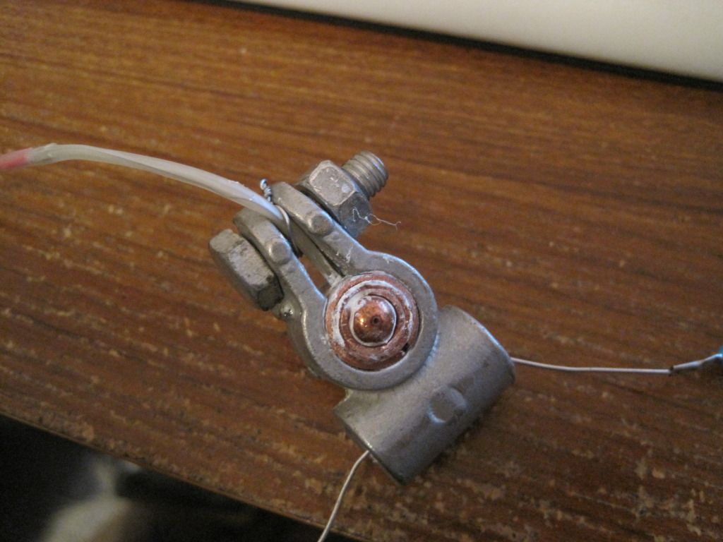
I fitted the sensor as far into the hole as it would fit, and held it in place with a small peice of wire.


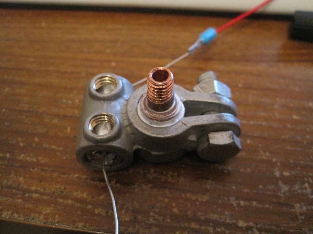
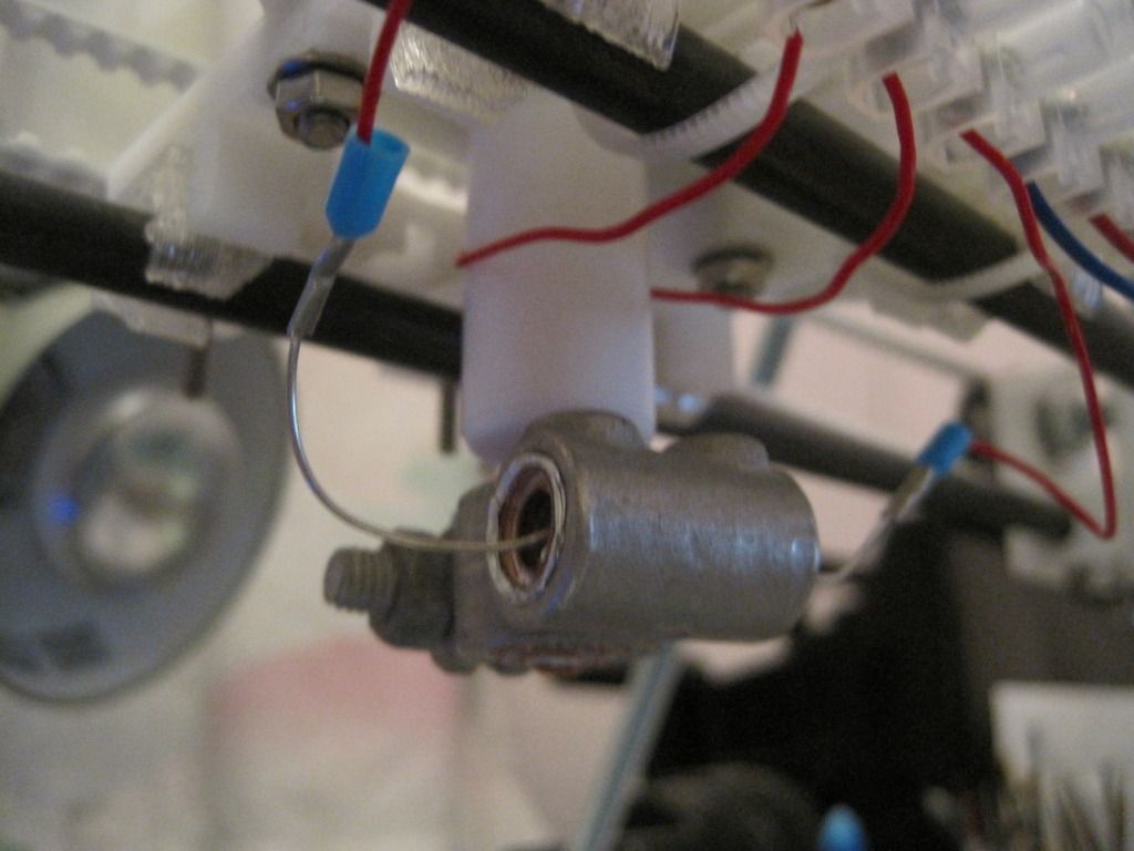
I screwed the mig tip into the barrier, and tightened it up. Then I fitted the heater and thermistor wires into the terminal block, and competed the wiring to the board.


Next up: Will it actually work...?

Friday, 30 September 2011

Chapter 19 - In which there is life!

I've been spending a lot of time recently working on the hot-end, but I'm saving the writeup until I have it completed and can make a whole post.

In the meantime, I've made small amounts of progress in other areas.

I have completed the wiring of the stepper motors for the axes. I wired them all the same, and consequently had to invert the direction in the firmware. I have also resisted cutting down the motor cables for any of the motors. I feel like I might need them longer later, in case I want to swap a motor or something. I realise this is unlikely. I'll cut them down later, if I can get the courage to. In the meantime, the excess cable is neatly bundled with the motors, or on the frame.

Once I had all the motors wired up, I fired up ReplicatorG to move the axes and check the direction was correct. I encountered a strange bug, wherein the axes wouldn't move properly under manual control, sometimes only moving a short distance, and other times moving in reverse. Also sometime multiple axes moved at once! I don't know if this will effect the operation of the machine when printing, but I didn't like it.

I went off and installed Pronterface instead. After the fun I had with sprinter, I was expecting to have some trouble with Pronterface, but was pleasantly surprised. The install guide is concise, but it works perfectly. Printerface needs almost no configuration, and is very quick - I like it! Comes with built in skienforge support too, which is nice. Infact I then went off and got Sfact too, as the pair seem to go together well (pronterface has some sfact-exclusive options).

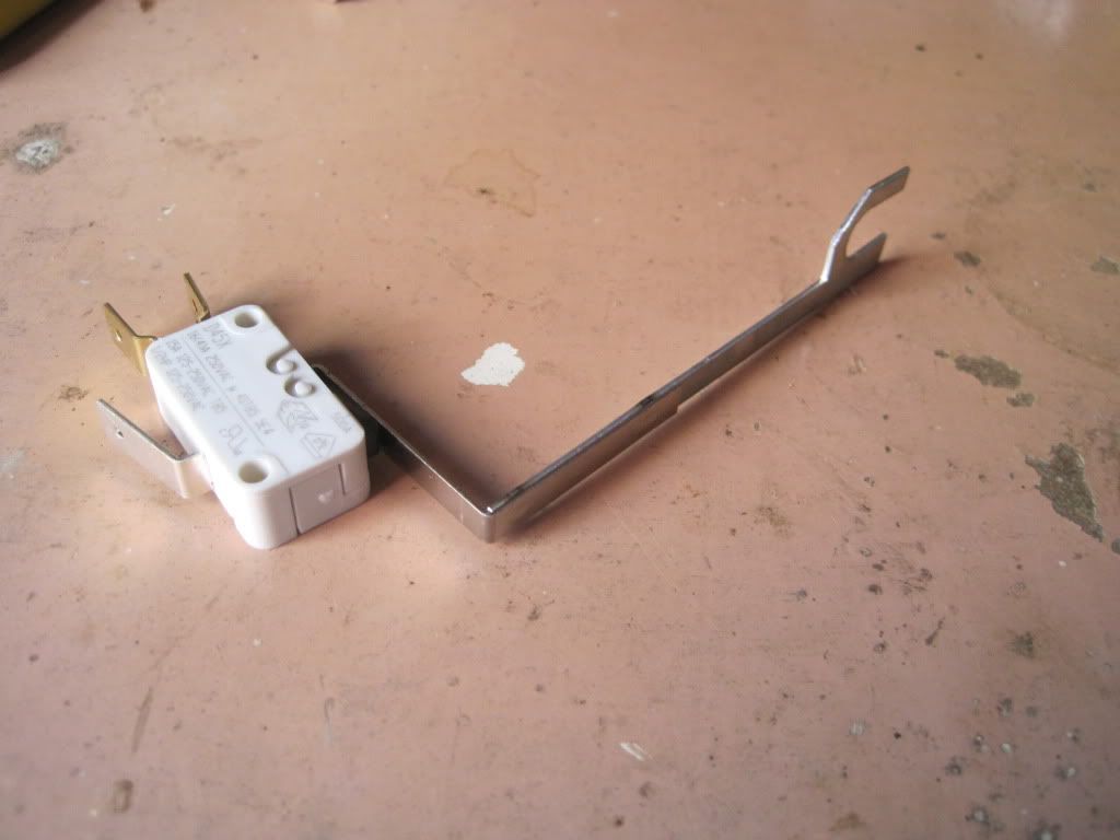
More recently I have added the endstops to the axes. I'm using microswitches, and they had arms on them:


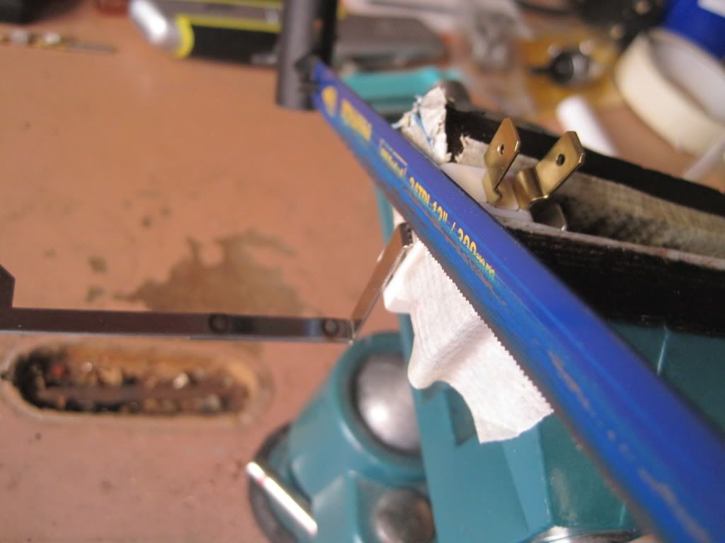
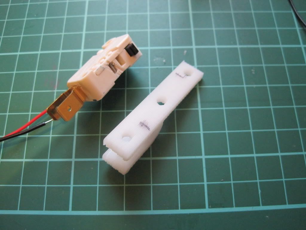
I popped them into the vice, and sawed off the arms - careful to avoid sawing off the switch!


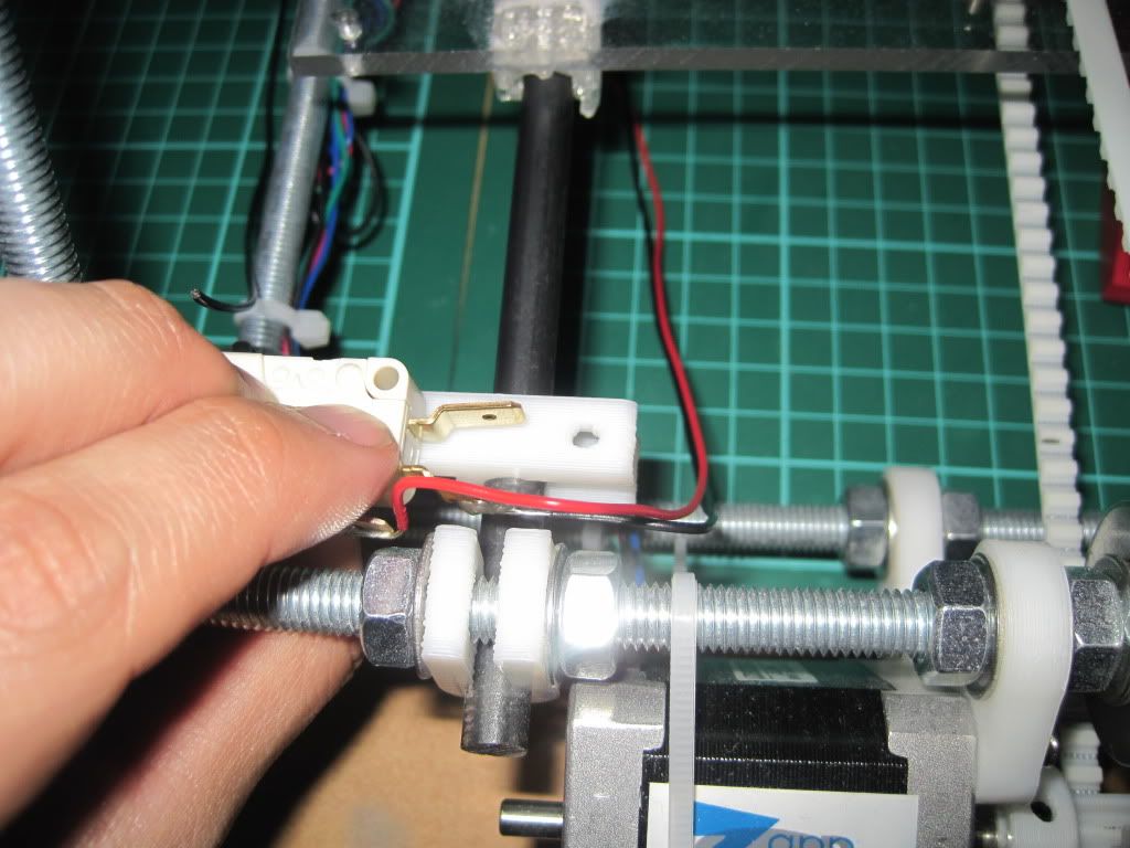
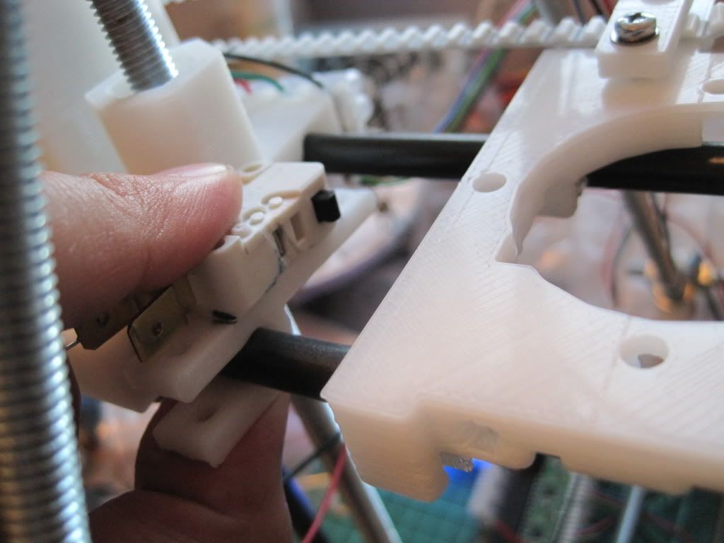
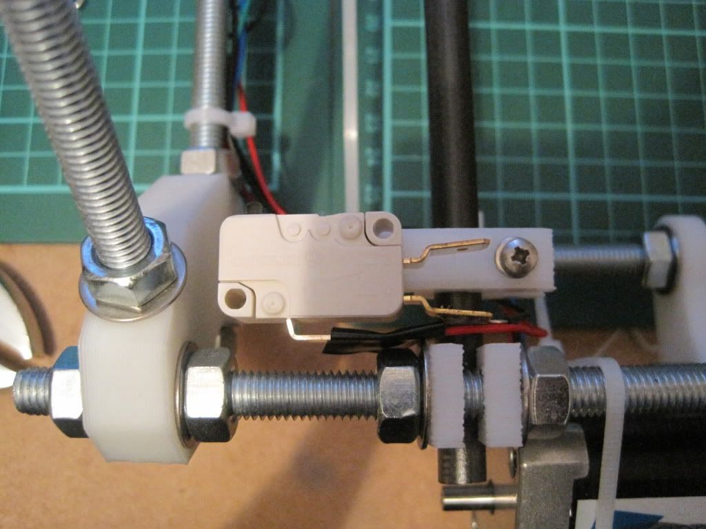
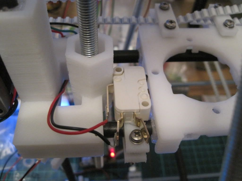
I decided on locations for the endstops. They are configured as being at the minimum end of the axis in firmware, and so this translates to Y being at the front, the X being at the left, and the Z at the bottom. I played around with locations for a while before marking up the brackets.


I attached the endstops to the brackets with hot glue, as the screwholes were in the wrong places. Each bracket was then fitted to the axis with an M3x25 screw, with a couple of plain washers and a spring washer.  I added some insulating tape to the Y axis terminal, so that it didn't short to the frame.


Once the endstops were installed, I wired them to the plugs and routed the cables along the frame.

I powered on the machine, and tested the endstops. I moved the axis out a long way, and then told it to return. As it was moving I activated the switch. All 3 axes worked ok, stopping the moment the switch was pressed. I then told Pronterface to "Home" the axes. It was pretty scary to watch, as the axes drove themselves into the stops:


In other news, I ordered some filament from Faberdashery. When I tried to load it into the extruder, disaster struck! The hobbed section of my bolt is too narrow, and the filament is too rigid to come into contact with it, regardless of how much pressure is applied by the idler.

I have to hobb a new bolt. I have ordered some M8 by 60 shoulder bolts from ebay, and will hobb the shoulder with an M6 tap - if I can work out a way to do it.

Next up: not sure. Maybe the hot end.

Sunday, 11 September 2011

Chapter 16 - In which I seize power from the bin-men.

I had initially planned to pick up an Xbox 360 power supply to drive my machine, but it has come to light recently that they aren't too good when it comes to instantaneous loading. I decided to look around for something else.

I had already build the sanguiniololu board with the screw terminals and 5V regulator fitted, rather than the ATX parts. It is believed that the 5v line on ATX power supplies isn't as smooth as it could be. Still, I figured that I could use the 12v output from a similar supply and feed that into the regulator. That should supply smooth(er) 5v to the low power side, and 12v to the high side without a massively high voltage on the inputs.

It just so happened that work was in the process of throwing out a load of old IT equipment. I raided the waste electricals skip and came away with a couple of (hopefully) identical ATX power supplies. They're rated to 185 watts max, and can deliver 10A over the 12 volt line, which should be enough to get started with. I will run the machine from one, and perhaps use the other to power the heated bed, when I build one.


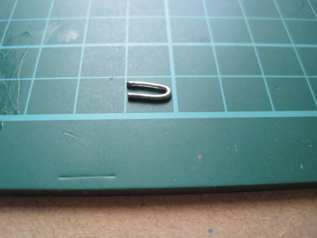
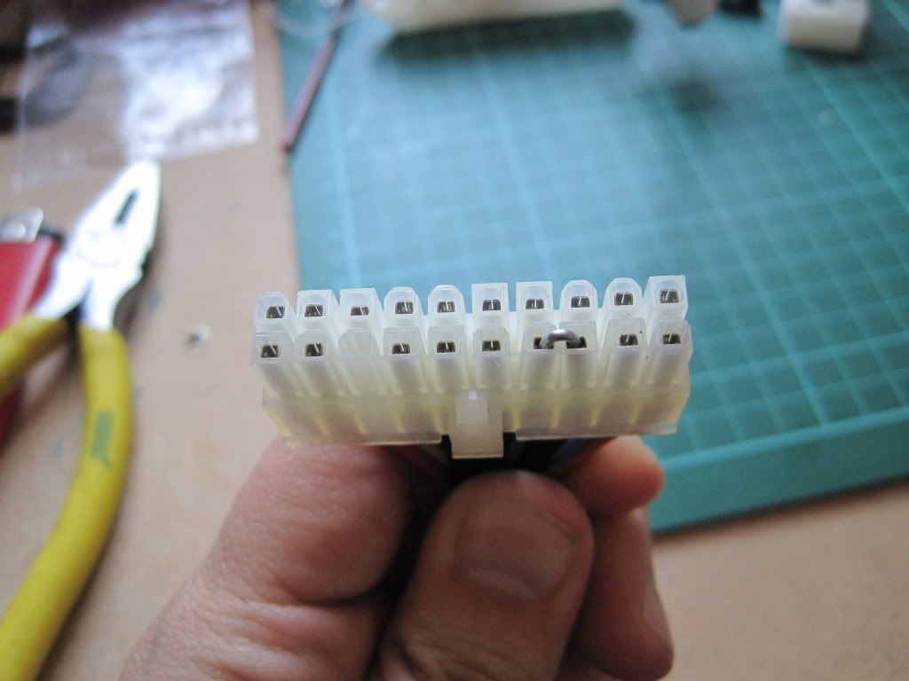
The reprap wiki has a page on using PC power supplies. ATX supplies have a power sensing circuit, and so to make it work I took a section of paperclip and bent it:


I used a fairly thick one to keep the resistance down. It links the green "power sense" pin to a black ground pin, thus turning the supply on.


This is a temporary solution - I will put in a proper switch at a later date, along with tidying up the extraneous wiring.

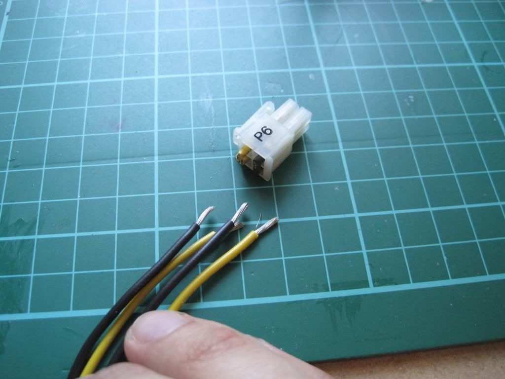
I took the high-current ATX-4 connector, and took (cut) off the plug. I stripped the ends and twisted the yellows (+12v) and blacks (ground) together. They will go into the screw terminals.


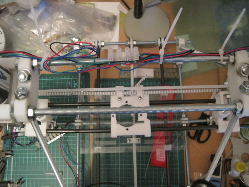
Lastly I stared to wire up the motors. I used some terminal block on the top rods to link the Z motors in parallel. I twisted the ends of the motor cables together, and fed them into one side of the terminal block. The other side is fitted with cabling that runs down the side of the frame vertex to the back-left of the machine, where the electronics will live.


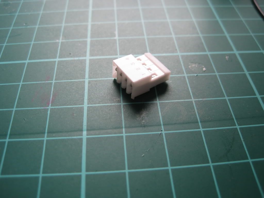
I'm using "amp" insulation-displacement plugs to connect the motors etc to the PCB.


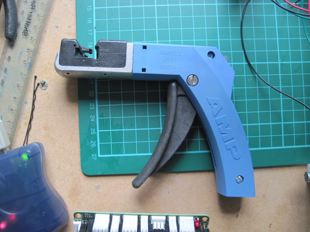
I borrowed an "amp-gun" criming tool, and crimped the cables into the plug.


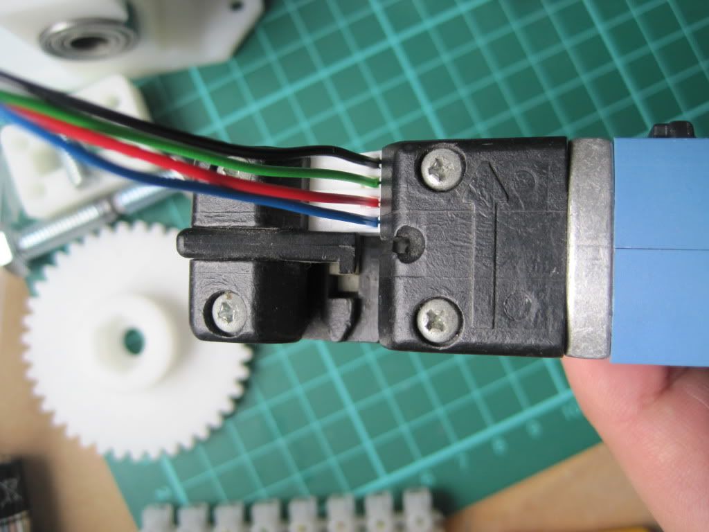
To connect the motors to the board, the wires to each coil have to be next to each other. I checked the datasheet for my motors, and put the black and green together, and the red and blue. Lastly I used a CD marker to label the plug "Z".

Next up: that pesky bootloader.