Showing posts with label prusa. Show all posts

Sunday, 16 October 2011

Chapter 20 - In which problems are rectified, and I make a temperature sensor the professional way

Its been a while since my last post. This is due to having had a week away in Scotland, but also due to progress being slow. I have however made some progress.

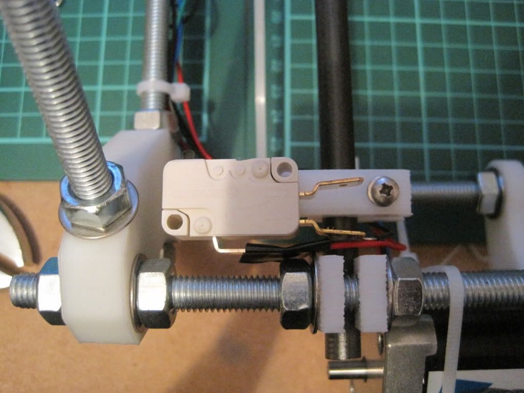
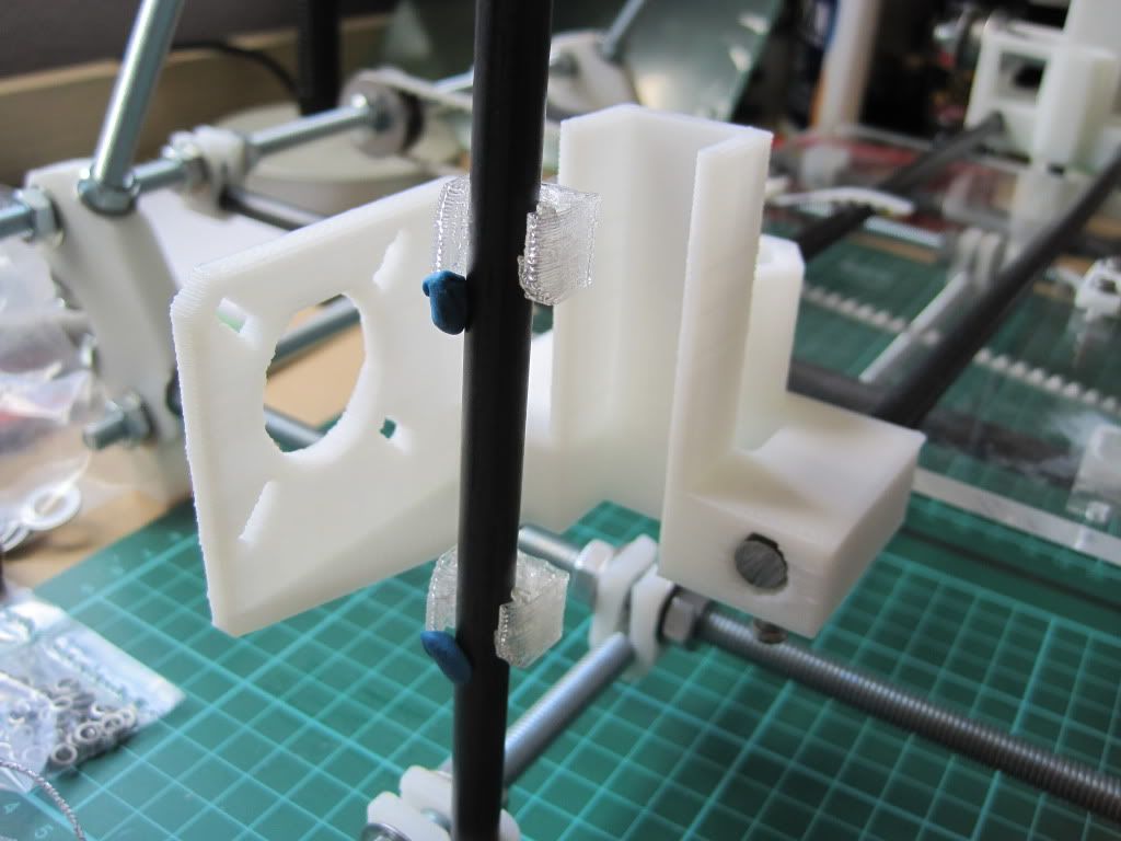
Firstly I changed the angle of the X-axis endstop. I had test-fitted the extruder body, and found the endstop was in the way. There is a conveniently provided little square protrusion on the side of the carriage, and the contact of the realigned endstop sits nicely on it.

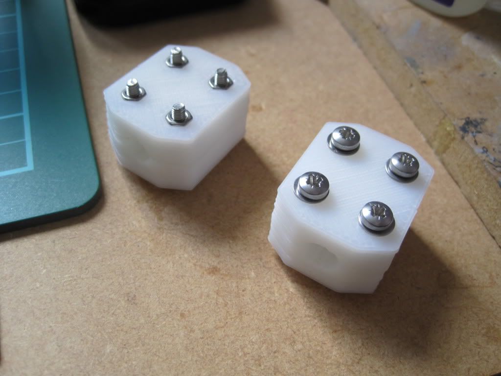
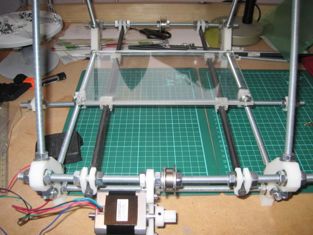
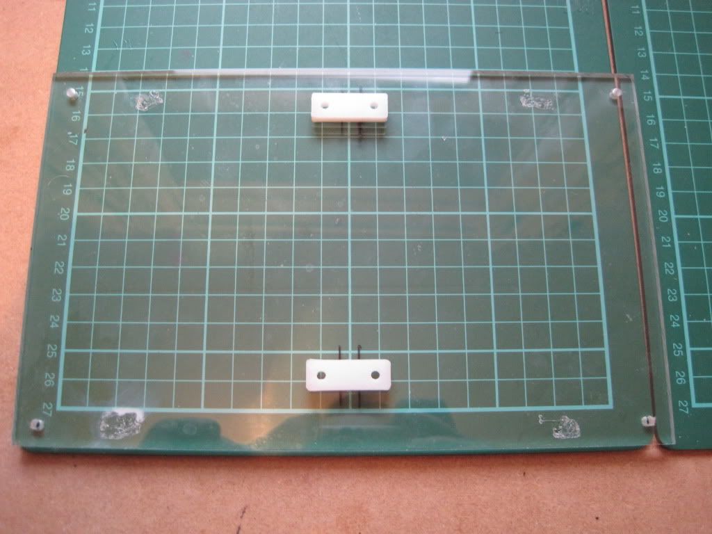
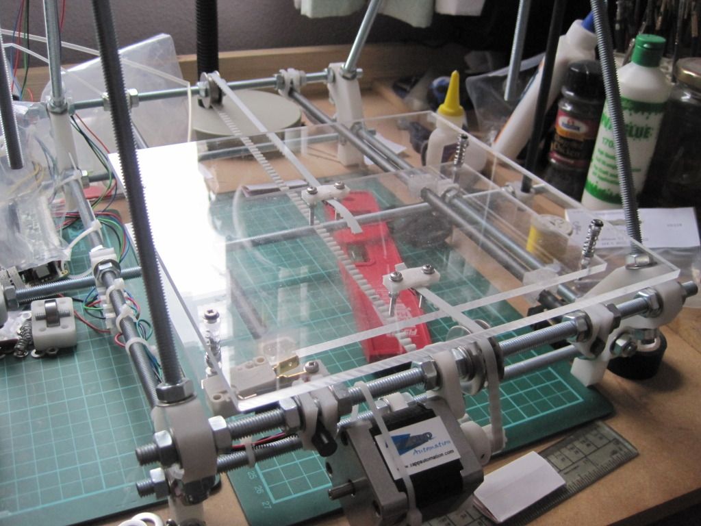
I then proceeded to fit the print bed. I had spotted this post on the forum, and decided to make the upgrade now rather than later. I had also got lots of peg springs just waiting for a use. I have used countersunk screws to mount the bed, but only because they were the only ones I could get with the correct length. There are washers under the heads to prevent the screws pulling into the bed and cracking it.
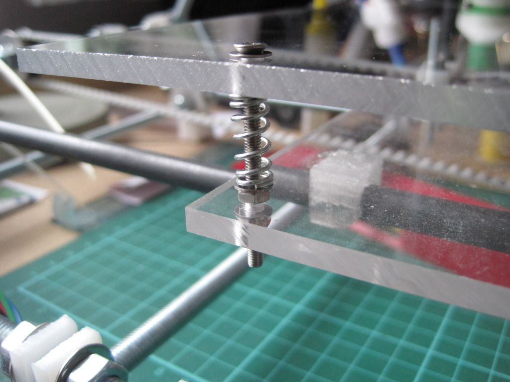


The bed is fairly level as it is, but I may tighten up the nuts to compress the springs, making the bed firmer and less prone to wobble. This has the added advantage of giving some extra Z height.


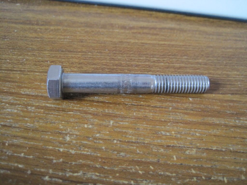
I had ordered some replacement bolts to hobb, as the previous one was too narrow. Once they turned up, I spent an evening in the garage attempting to hobb one of them. It was much harder going than the previous bolt - maybe these are made of something harder? I was also trying to hobb with an M6 tap as opposed to an M3, to give bigger teeth on the bolt. I just couldn't get it to cut the teeth correctly, and it left an un-cut section in the middle of the bolt. I ended up getting very frustrated with it, and walked away trying to decide how to go about making one properly.

I came back to it a week or so later, and had a proper look in the daylight. The hobbing down one side looked pretty good, and fairly even. I figured that I could probably space the bolt such that the good section was doing the driving.


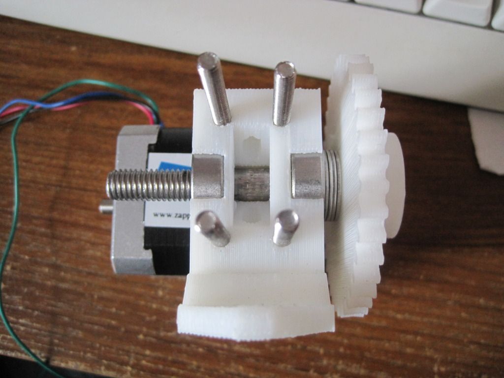
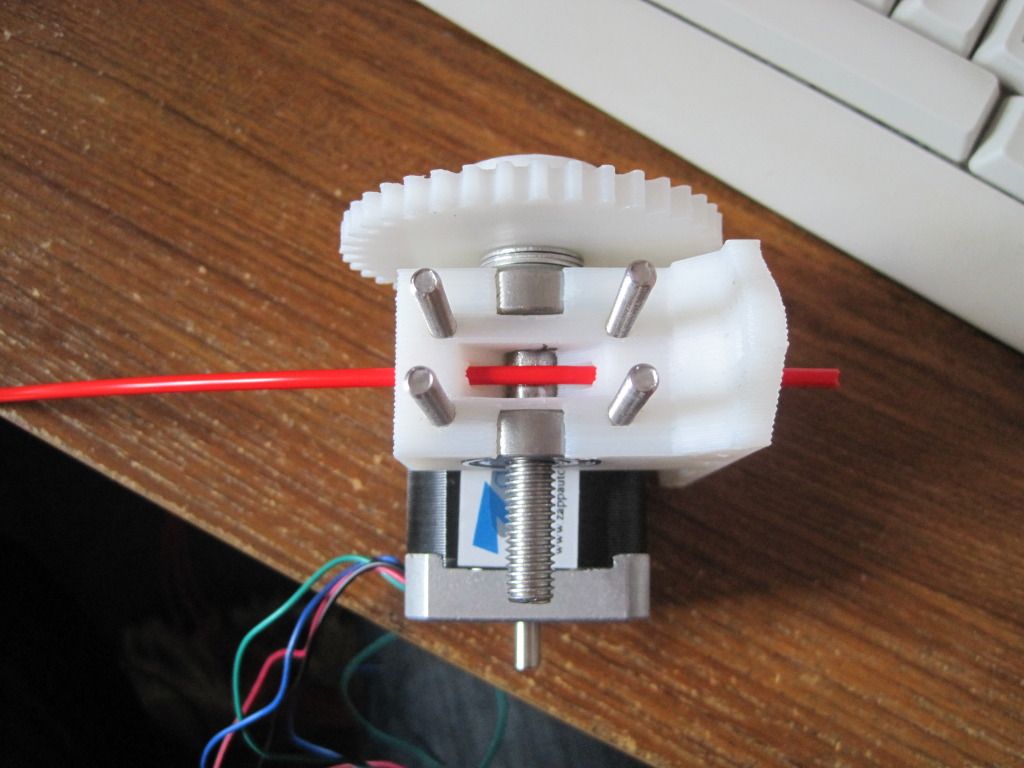
I put the extruder back together, and was pleasantly surprised to find that the good section was in the correct place already. Better than that, it had enough grip to drive feedstock without the idler in place! Whilst working on the extruder, I also moved the motor and fitted the bolts that will mount the extruder to the X-carriage. I reassembled the extruder and idler, and repositioned the motor to get the best interface between the gears.

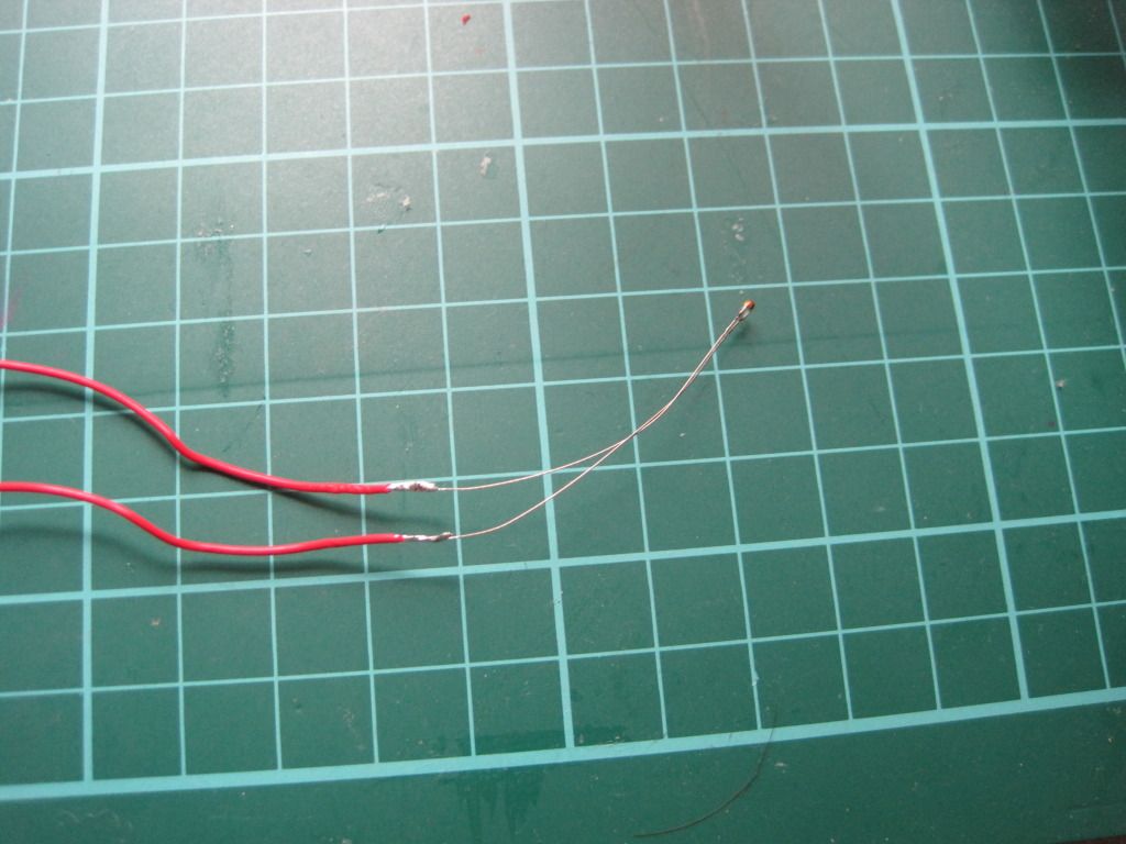
I also had the time to make up the hot-end temperature sensor. I constructed this in a similar manner to how professional temperature sensors are made. Firstly I soldered the ends to the stripped ends of the PTFE wire:


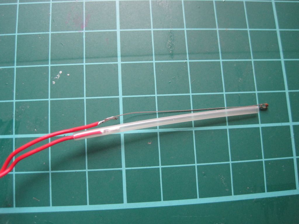
I then used high-temperature heat-shrink sleeving to insulate one leg, all the way from the small joint at the thermistor head to past the solder join:


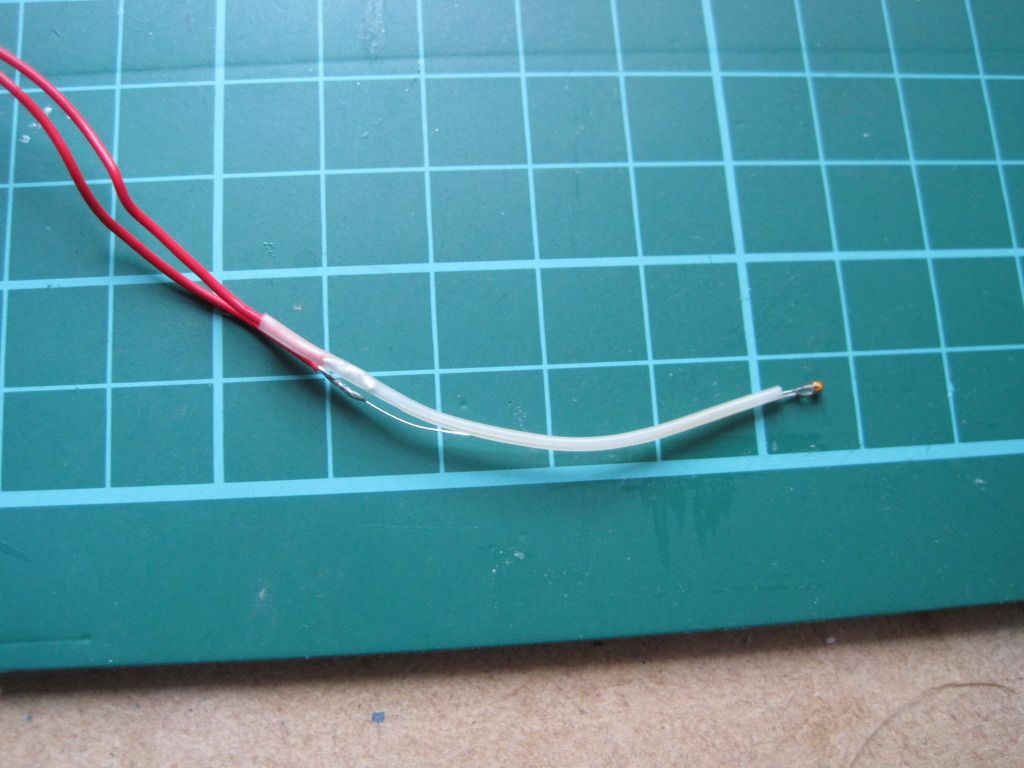
I shrunk the sleeving with the kind help of my girlfriend and her crafting hot air gun:


I then used a larger diameter piece of the same sleeving to cover the entire assembly, from a point past the thermistor head to past the remaining soldered joint.
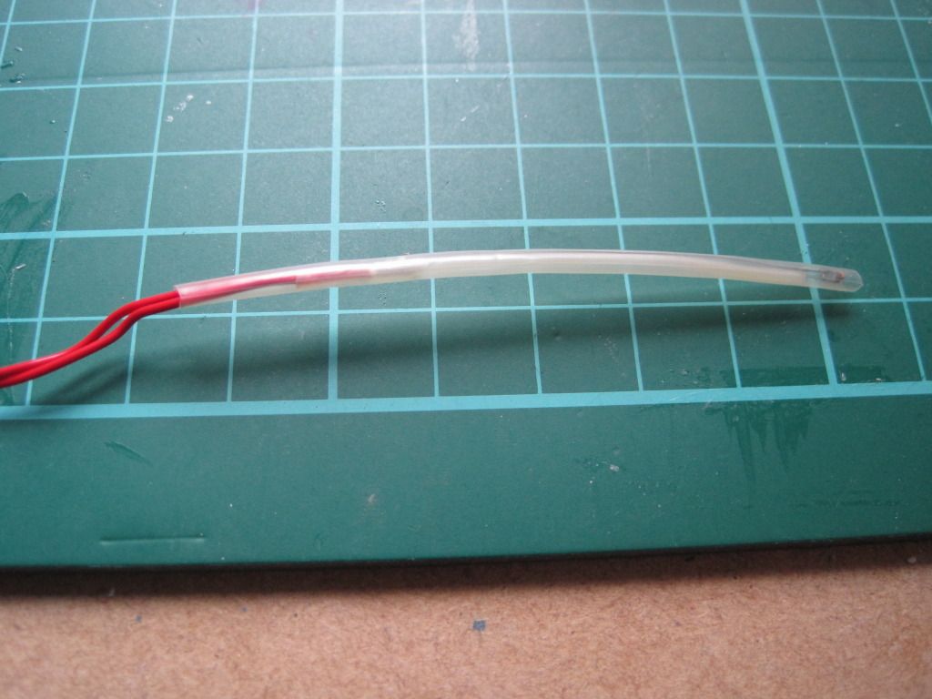
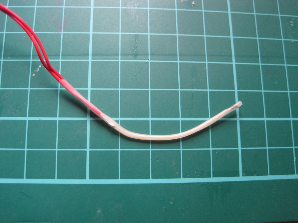


Lastly I trimmed the overhanging sleeving close to the bead. This assembly method should provide a robust and short circuit-free sensor for the hot end.

And Thats all the I've managed to achieve. Next up: The long-awaited hot-end post?

Friday, 30 September 2011

Chapter 19 - In which there is life!

I've been spending a lot of time recently working on the hot-end, but I'm saving the writeup until I have it completed and can make a whole post.

In the meantime, I've made small amounts of progress in other areas.

I have completed the wiring of the stepper motors for the axes. I wired them all the same, and consequently had to invert the direction in the firmware. I have also resisted cutting down the motor cables for any of the motors. I feel like I might need them longer later, in case I want to swap a motor or something. I realise this is unlikely. I'll cut them down later, if I can get the courage to. In the meantime, the excess cable is neatly bundled with the motors, or on the frame.

Once I had all the motors wired up, I fired up ReplicatorG to move the axes and check the direction was correct. I encountered a strange bug, wherein the axes wouldn't move properly under manual control, sometimes only moving a short distance, and other times moving in reverse. Also sometime multiple axes moved at once! I don't know if this will effect the operation of the machine when printing, but I didn't like it.

I went off and installed Pronterface instead. After the fun I had with sprinter, I was expecting to have some trouble with Pronterface, but was pleasantly surprised. The install guide is concise, but it works perfectly. Printerface needs almost no configuration, and is very quick - I like it! Comes with built in skienforge support too, which is nice. Infact I then went off and got Sfact too, as the pair seem to go together well (pronterface has some sfact-exclusive options).

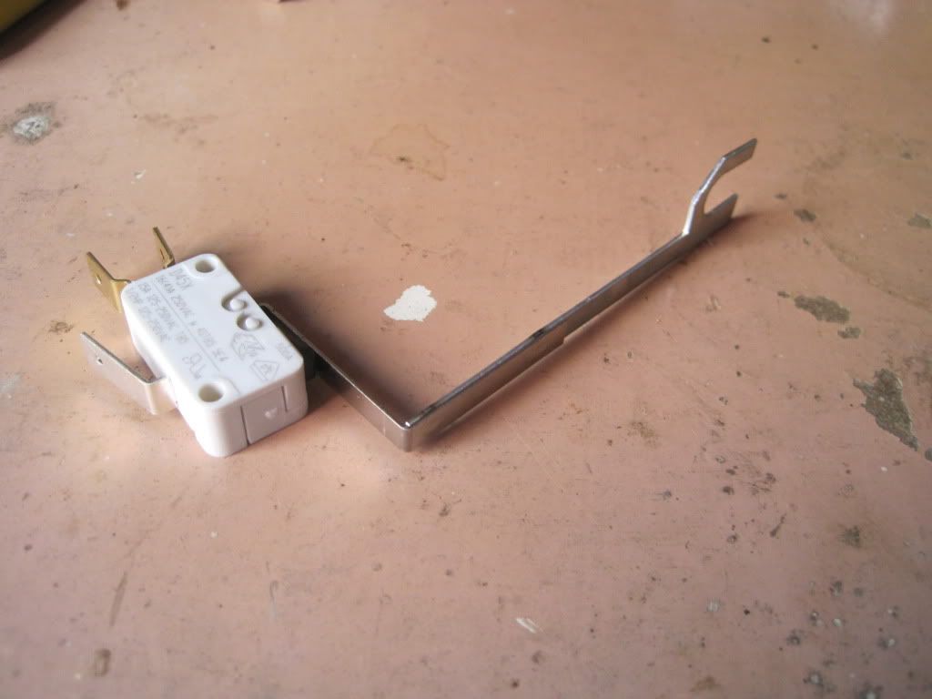
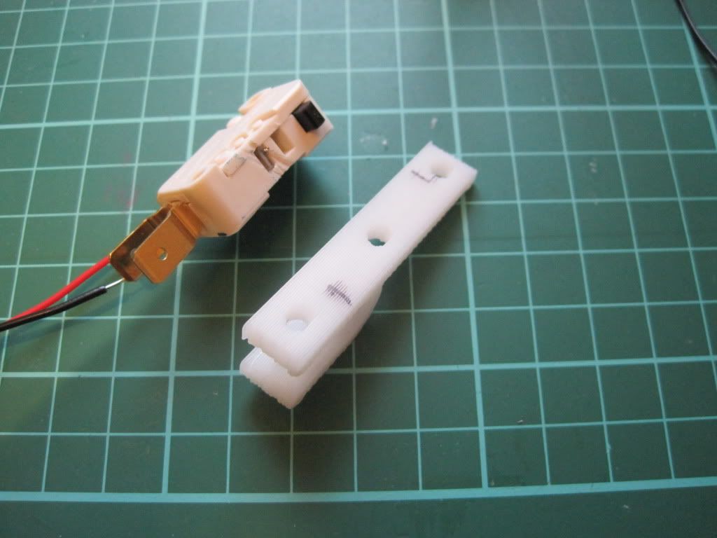
More recently I have added the endstops to the axes. I'm using microswitches, and they had arms on them:


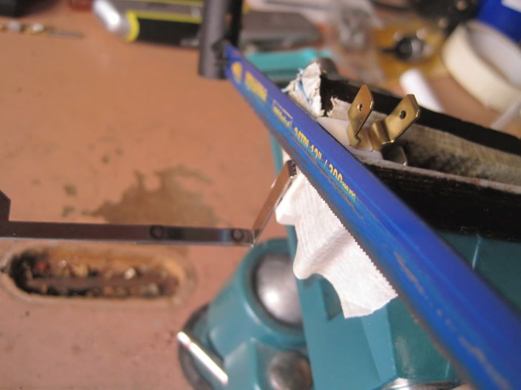
I popped them into the vice, and sawed off the arms - careful to avoid sawing off the switch!


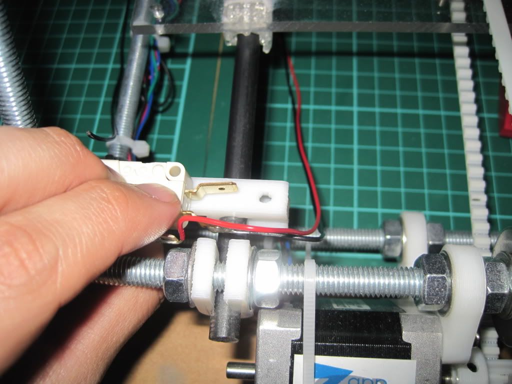
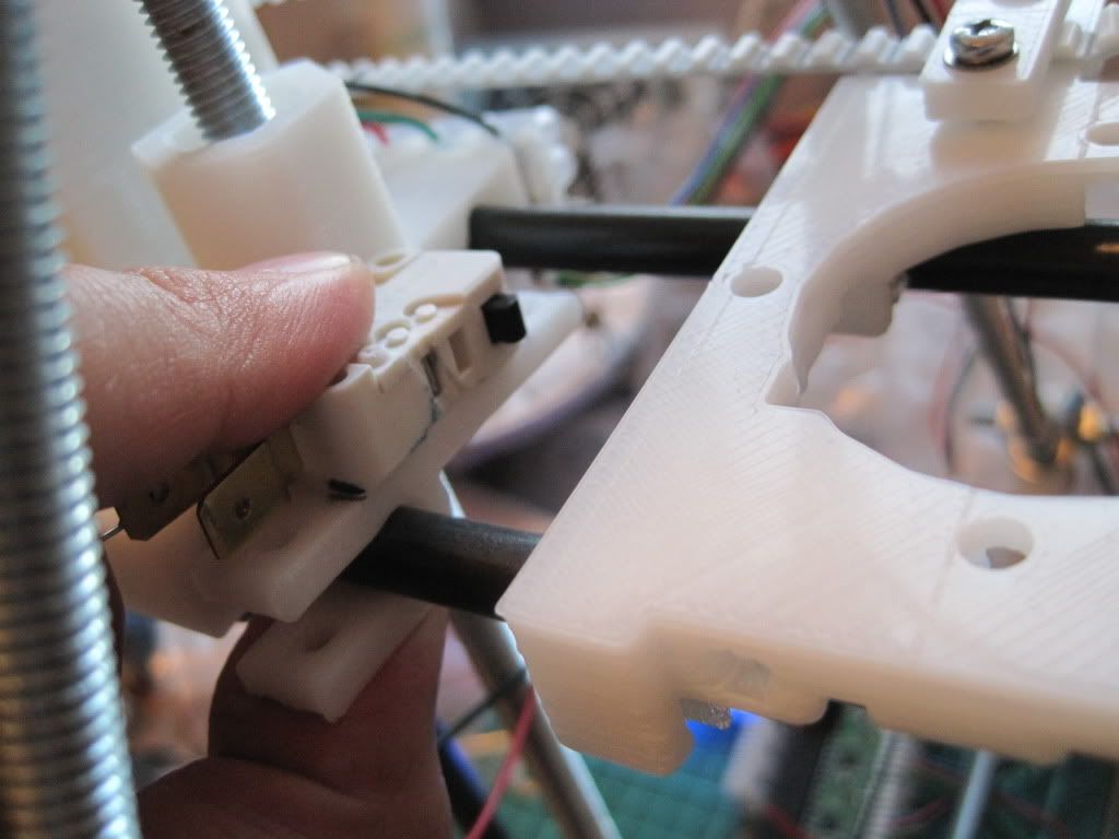
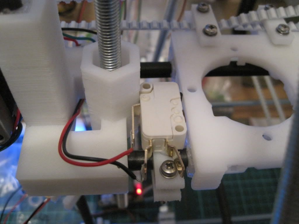
I decided on locations for the endstops. They are configured as being at the minimum end of the axis in firmware, and so this translates to Y being at the front, the X being at the left, and the Z at the bottom. I played around with locations for a while before marking up the brackets.


I attached the endstops to the brackets with hot glue, as the screwholes were in the wrong places. Each bracket was then fitted to the axis with an M3x25 screw, with a couple of plain washers and a spring washer.  I added some insulating tape to the Y axis terminal, so that it didn't short to the frame.


Once the endstops were installed, I wired them to the plugs and routed the cables along the frame.

I powered on the machine, and tested the endstops. I moved the axis out a long way, and then told it to return. As it was moving I activated the switch. All 3 axes worked ok, stopping the moment the switch was pressed. I then told Pronterface to "Home" the axes. It was pretty scary to watch, as the axes drove themselves into the stops:


In other news, I ordered some filament from Faberdashery. When I tried to load it into the extruder, disaster struck! The hobbed section of my bolt is too narrow, and the filament is too rigid to come into contact with it, regardless of how much pressure is applied by the idler.

I have to hobb a new bolt. I have ordered some M8 by 60 shoulder bolts from ebay, and will hobb the shoulder with an M6 tap - if I can work out a way to do it.

Next up: not sure. Maybe the hot end.

Tuesday, 27 September 2011

Chapter 18 - In which my alternate spring source is validated

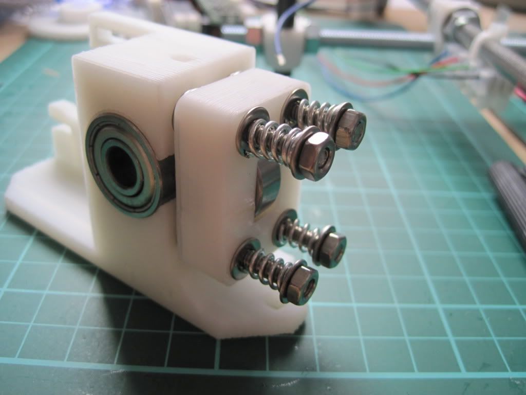
One quiet Sunday, I sat down to build my extruder. I had already hobbed the bolt, and so now only needed to build up the extruder body.

I had a little trouble fitting the bearings into the extruder body, but a little work with a file ensured that they sat flush:


I had a peice of threaded rod left over from cutting the frame bars down, so I cut it to 50mm and used it to mount the idler bearing. The bearing seems a little loose though, so I may have to change it out in the future.


I fitted M4 by 50mm bolts through the extruder body, and fitted a pair of washers to each one. I had to file out the screw holes a little to make the bolts fit.


I fitted the idler block over the bolts - this was harder that I had thought it would be, due to having to keep the block square or the bolts would bind up.

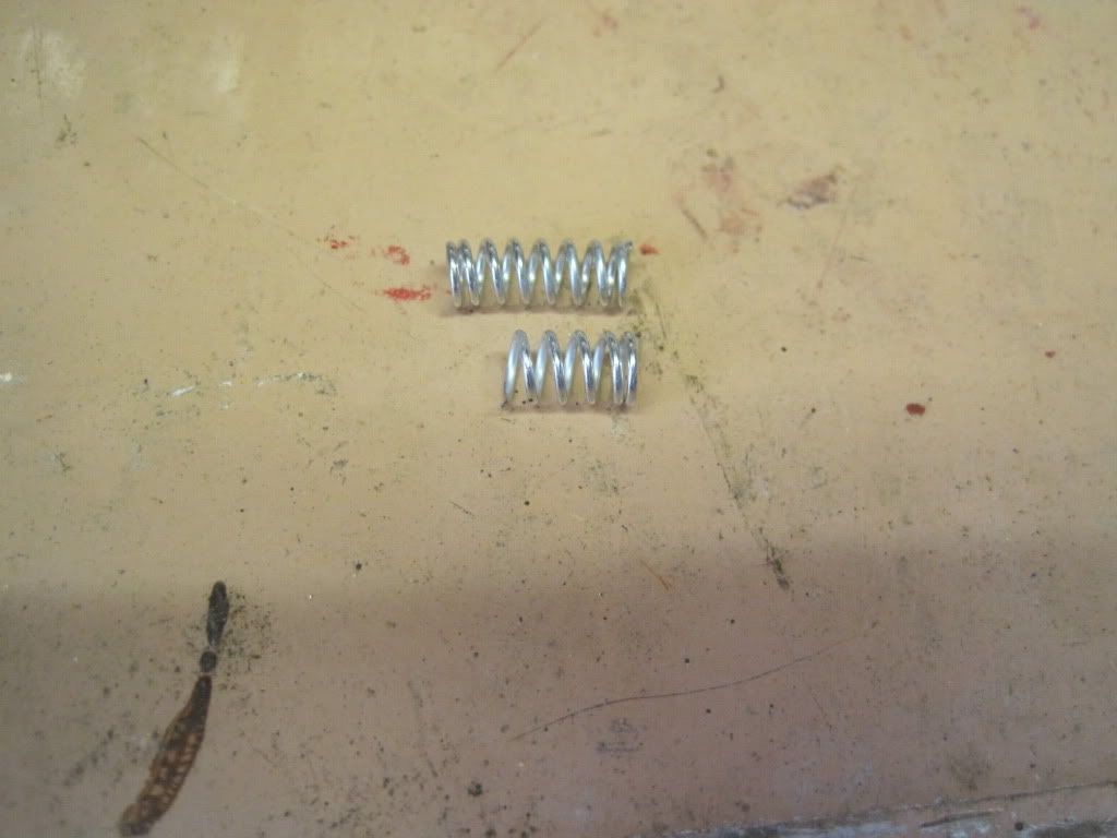
Now, time for the all important springs. As I mentioned here, I had found a source of springs in a certain shape of clothes peg. I had ordered some after scouring ebay for the right type. Unfortunately when they arrived they were the traditional, sideways-action spring type. I got in touch with the company, whoi were able to find some of the kind their listing showed. Lesson learned by me - some photos on ebay are for illustrative purposes only. Once I had the new, correct, pegs in hand, I set about de-springing them.


Having removed 4 springs, I was faced with another problem - they are too long for the bolts. After failing to compress them enough to get a nut onto the thread, I took them to the garage and took a hacksaw to them.  I cut them down to just the right length to allow them to be fastened on, with only a little compression.


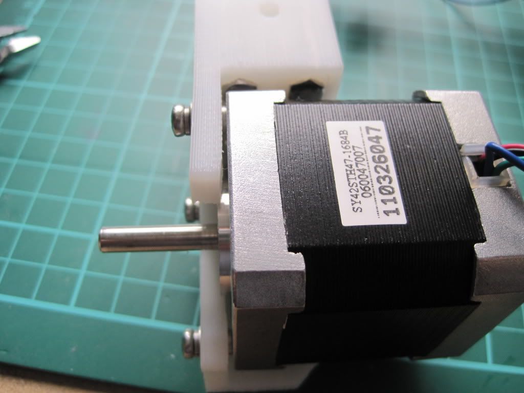
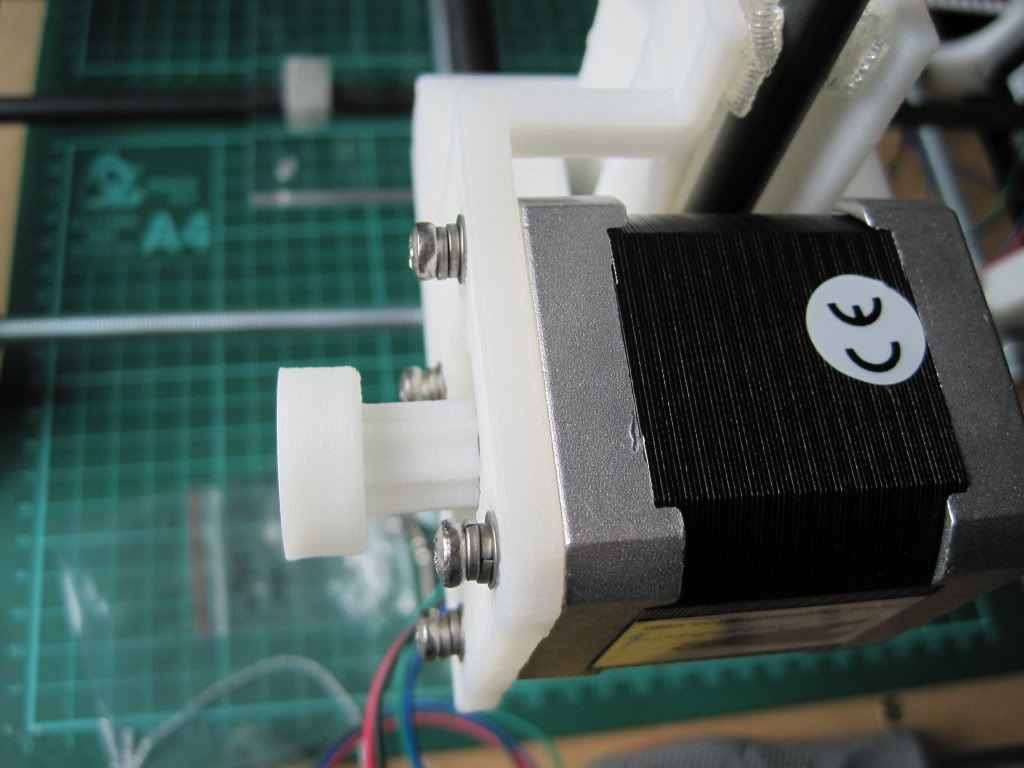
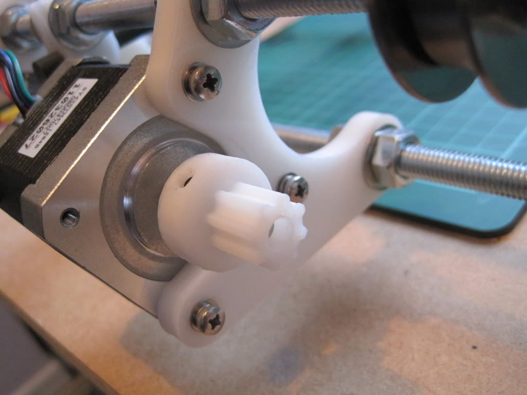
The motor mount on the extruder is thinner then that of the Y axis, so I though I could use the same trick of doubling-up the washers as I did on the x-end-motor. However, This made the Screw heads stick out too far, and they interfered with the gears. I opted for the solution below, with one set of spring washers between the motor and the extruder, and the other next to the screw heads:


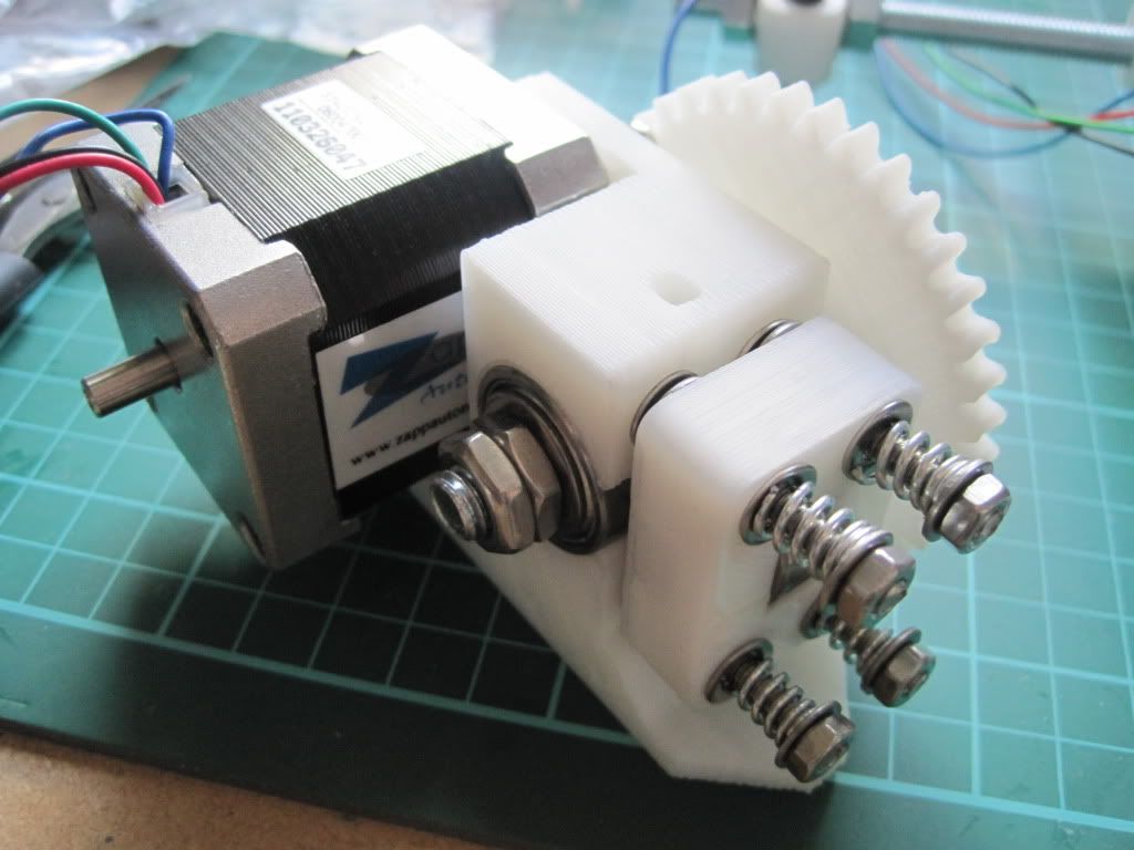
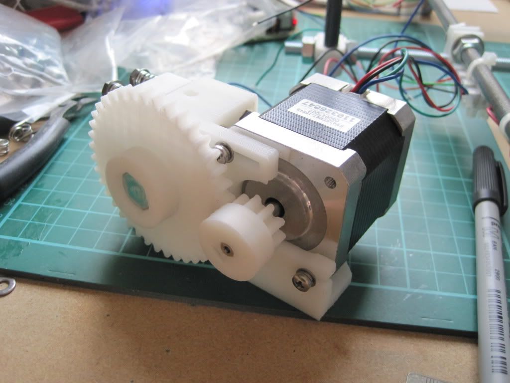
I fitted up the hobbed bot and large gear. I had to use 4 M8 washers to space the bolt correctly, because the hobbing had drifted to one side.


I had used a couple of M8 halfnuts that I found to hold the hobbed bolt in place, but have subsequently moved to one half nut and one full nut as I had problems getting the tension right and the locking tight enough.

Because of the extra washers spacing the big gear, I had to mount the small gear in reverse. This is actually suggested in some of the instructions, and won't cause any trouble due to the grub screw still being securely on the shaft.


Next up: talking to the machine

Thursday, 25 August 2011

Chapter 12 - In which I finish the X axis, and have a good idea

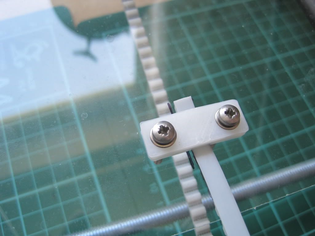
I wasn't happy with how the X carriage was travelling, and so I loosened off the smooth rods and rotated them (one at a time) until the carriage moved much more freely. I then fitted the belt clamps.


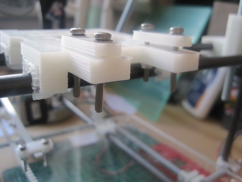
As you can see, the suggested M3 by 25mm screws are very long. In fact the back pair are so long they interfere with the smooth rods, and the carriage binds (this is probably due to how the carriage sits on its bushings). I replaced the rear screws with a pair of 12mm ones taken from the X axis ends (which were too long in the X ends anyway, and were replaced with some M3x6 screws I had found in a draw earlier).

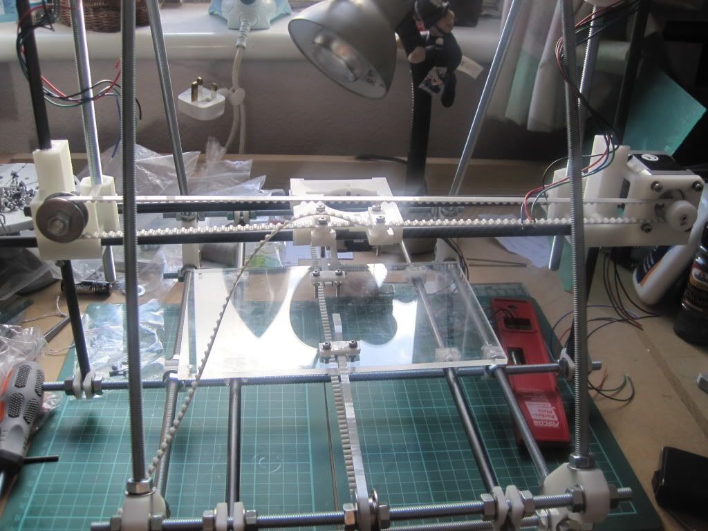
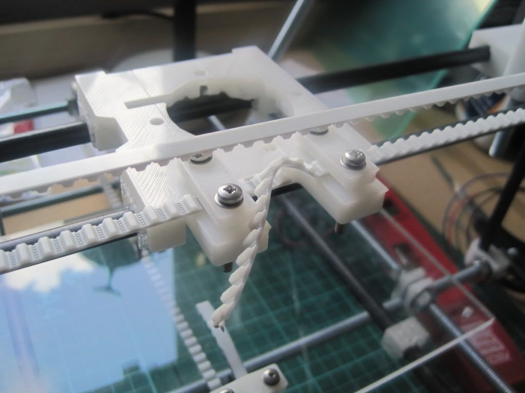
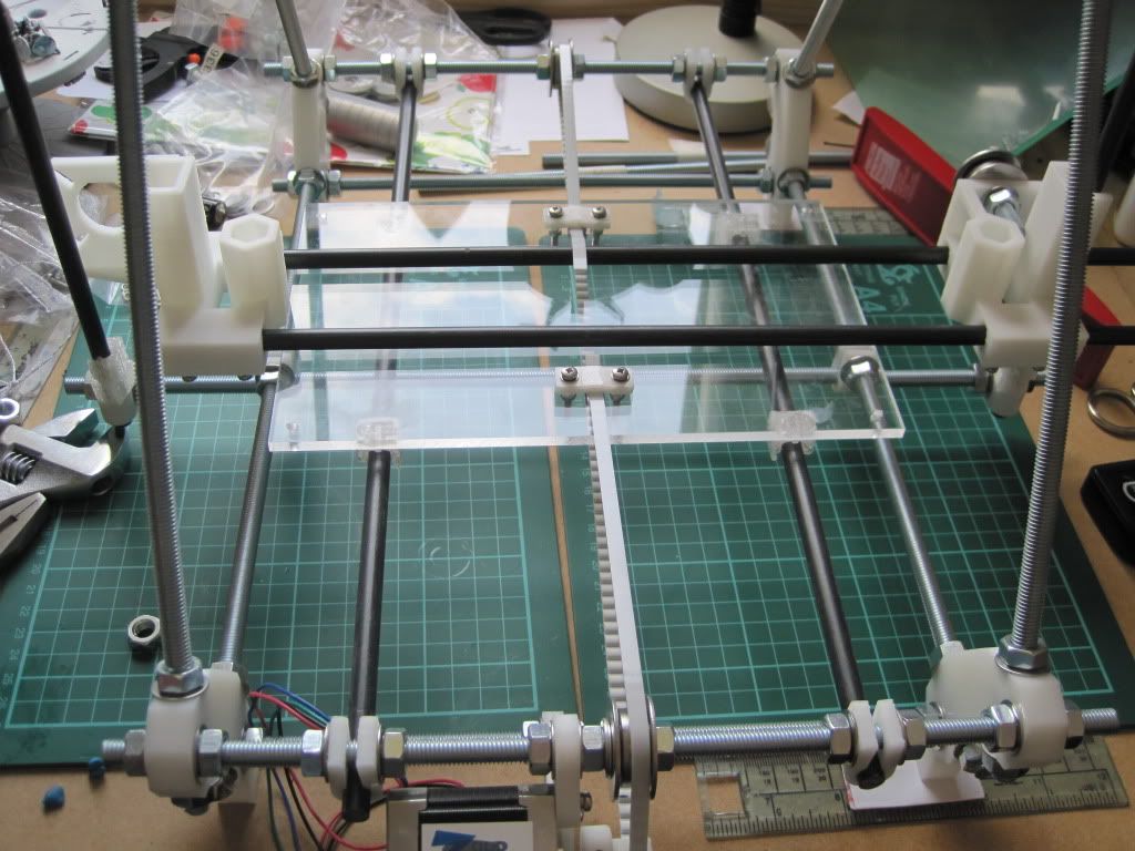
I fitted the X belt in the same orientation as the Y, namely with the teeth facing downwards in the clamps. It was only when I threaded the rest of the belt around the idler and back that I noticed that it was wrong - the teeth should face upwards, and the belt travel above the carriage rather than under it. I reassembled it and tightened everything up. The carriage now moves very smoothly, seemingly with no backlash.


I cut the belt off leaving a little for adjustment later if needed.


And that's as far as I can go today. Next I will build the electronics, but I need a PSU before we have any movement. I can also build the extruder once I get a few more bits delivered.

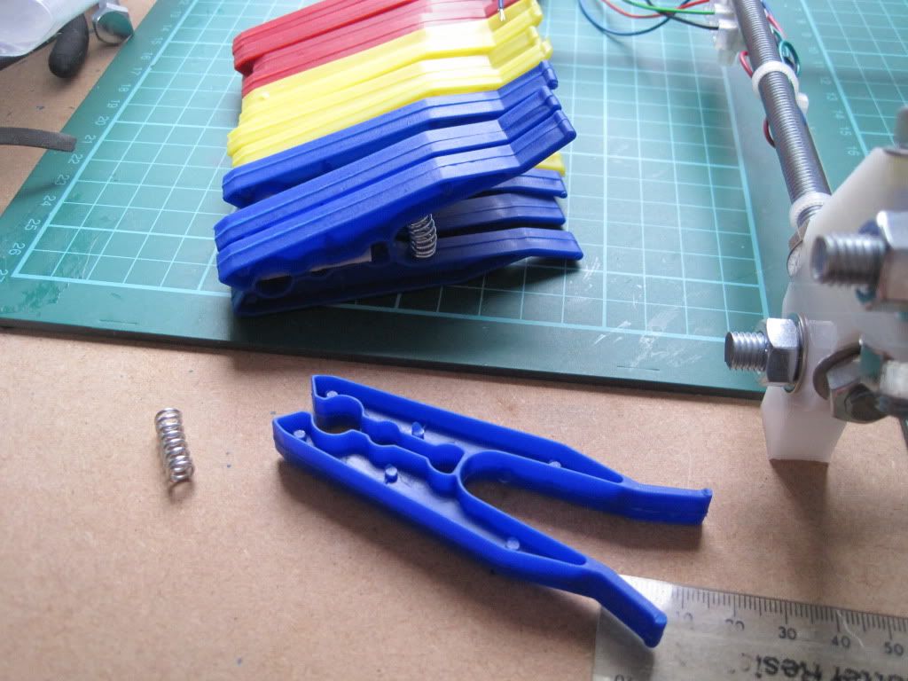
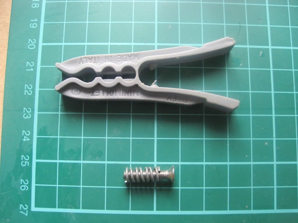
Whilst in the draw that yielded the earlier M3x6 screws, I also found the solution to the spring problem. I had previously been unable to find a cheap source for the springs needed to tension Wade's idler bearing in the extruder. I found this clothes peg, the spring from which is perfect:


I scoured ebay and picked up a pack of 24 for £2.50 - that's just over 10 pence each, a marked improvement on the £1 or £2 each I had previously seen springs going for.

Next up: Electronics build

Wednesday, 24 August 2011

Chapter 11 - In which more gets built, and I spot another potential problem

Encouraged by the progress made on Thursday, I pushed on on Friday. I started by fitting the belt mounting clamps, and the Y axis belt. This turned out to be pretty tricky, and during the fitting and tightening process I had the printer on my knees and upside down at least twice. Eventually I got everything tight and the belts with (hopefully) the right amount of tension in them.


Next it was time to fit the X axis to the vertical rods. I used the bottom plate to hold it horizontal whilst I manoeuvred the bushings into place. I held them in place with blue-tac while the glue dried.


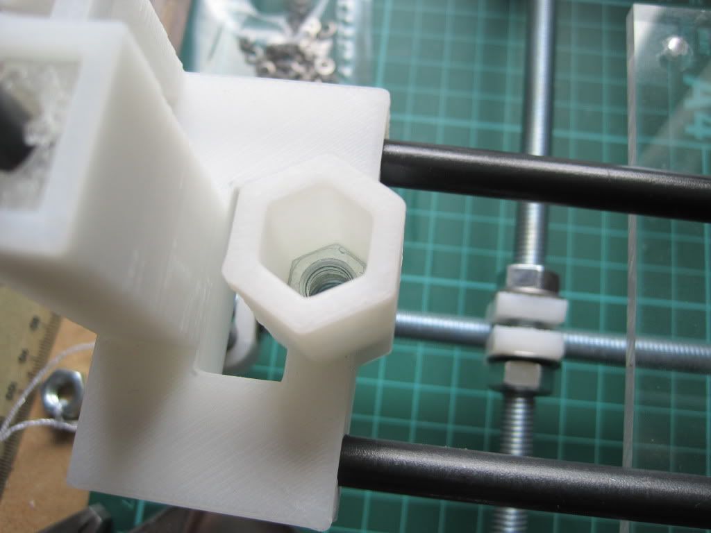
I left the screws on the X rods loose whilst the bushings were gluing, and tightened them up afterwards. Whilst the glue was drying, I made up the Z leadscrew clamps. These are the alternate clamps supplied by Nophead, and require additional M3x20 bolts, nuts and washers.


I screwed them together taking care to make sure they were the right way round.


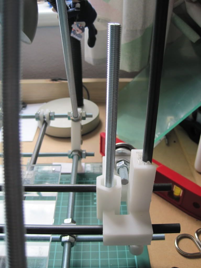
Once the glue on the bushings was dry, I added the nuts to the axis ends that will hold the leadscrews. The instructions don't make it clear whether the top nut is required if you are not using the springs (which I am not). I fitted it anyway, and will remove it if it causes trouble later.


I screwed the leadscrews home, and was about to fit them to the clamps when I remembered I needed to add the tubing.


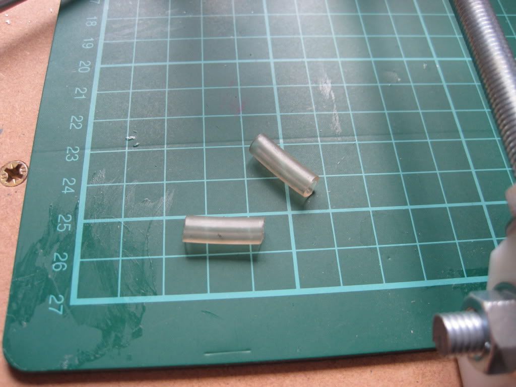
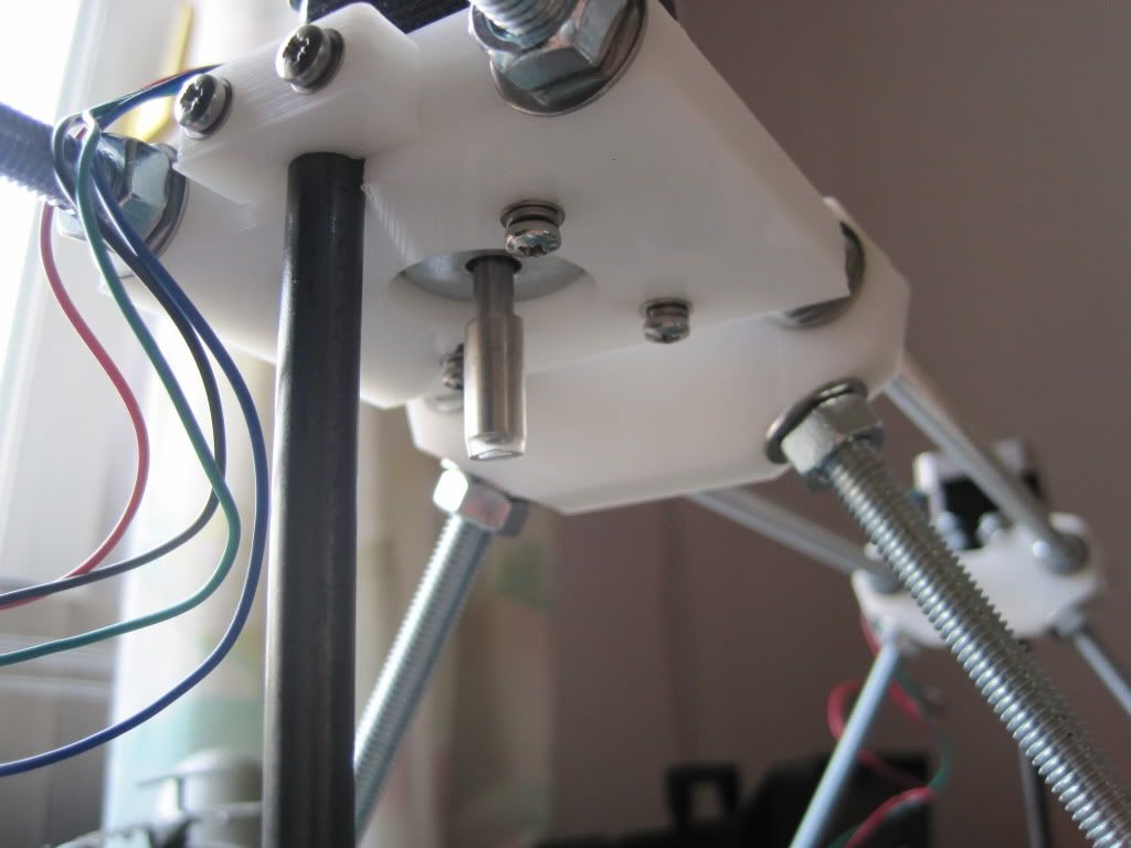
This goes around the motor shafts, and helps to eliminate wobble when used with the new clamps. I would recommend fitting it to the motor shafts before fitting the motors, rather than after - it would have been much easier! I had also fitted the motors with screws and washers, and decision that would come back to haunt me a little later.


I fitted the couplers to the motor shafts, and then propped the gantry on a small box so that I could screw the leadscrews into the couplers.


I screwed the leadscrews as far into the coupler as they would go without being forced, and tightened the screws. The coupling feels very solid and secure now it is all done up - I doubt I'll have any trouble with them coming undone or breaking! I removed the box and levelled the gantry.

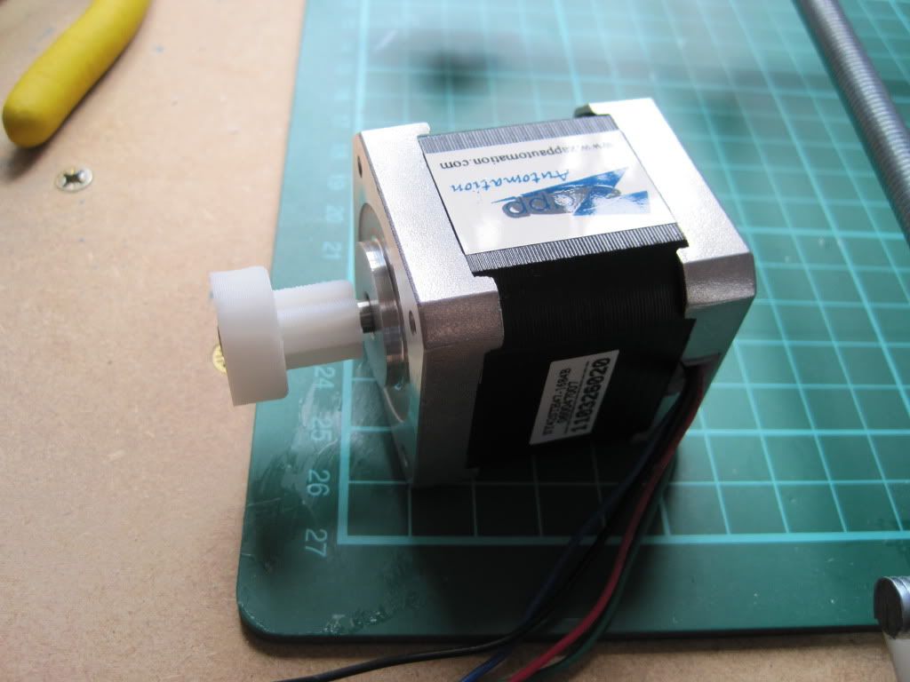
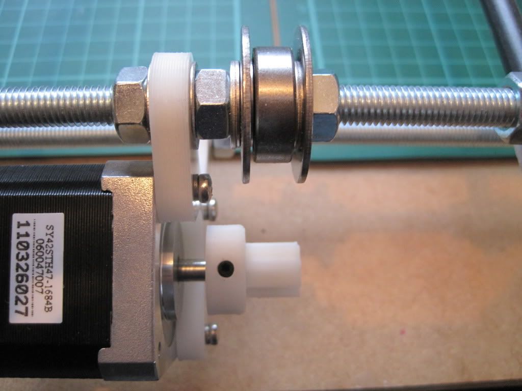
The next job was some work on the X axis. I fitted the pulley to the motor.


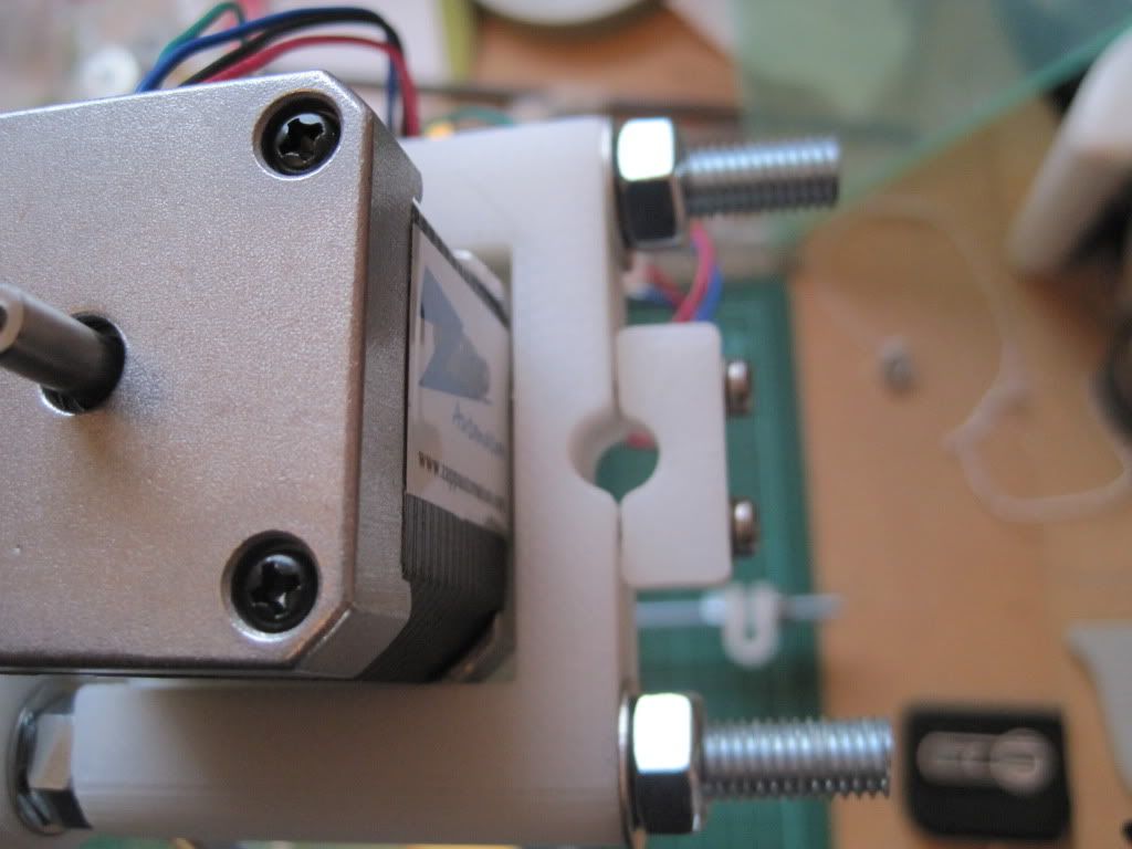
Then I tried to fit the motor to the axis end. However due to some mis-calculation somewhere, I had run out of M3x12 screws. I removed a pair from each of the Z axis motors (I'll replace them later), and used them to fit the X axis motor in place. The "bulkhead" that mounts the motor to the x axis end is thinner than the Y and Z axis mounts, and the screws bottomed out. I added an extra spring washer to each one and tightened them up.


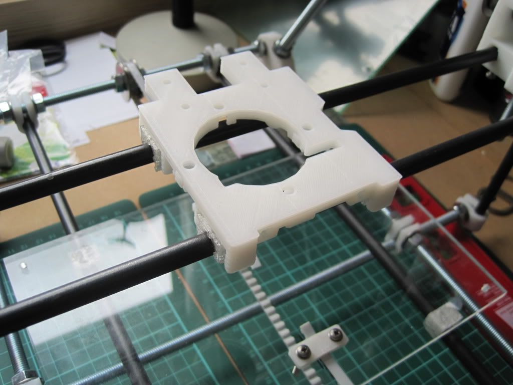
Lastly I snapped the remaining bushings in place and glued the X carriage to them.


Lastly, the problem I mentioned earlier. While mounting the X axis to the leadscrews,  I noticed something was a bit wonky. It looks as if the lower bed plate may have shifted whilst it was re-gluing, and has become wonky. I really don't want to have to do it again, but might have to if it is too bad. I'll wait until I fit the upper bed to see how badly misaligned it is.

Next up: fitting the X belt.

Thursday, 18 August 2011

Chapter 10 - In which I cheat a little, and things get back on track

Things are starting to look up - I now have all of the parts I need to finish my reprap, with the exception of some hot end bits (I think). The major cause of the delay was bought on by myself. In a bid to reduce the cost and number of surplus fixings I'd be left with, I opted to purchase the majority of the components I need through the company I work for. We use a vast array of fixings and electronic components, and I was able to get hold of almost everything I needed. Placing the order, and picking all the parts too longer than expected, but now it is all done I can crack on with the build.

Here are the majority of the parts I purchased:

Mechanical parts
Electronics
The microswitches in the first picture have 90 degree arms on them, and will need to be modified before use as endstops. They were more expensive than most of the others I looked at on the web, but they are good parts. They're UL and CSA approved, and are rated to switch 15 Amps. Whilst I'll never need that much, it provides a margin for error, especially if I end up with a firmware that doesn't use the processor's internal resistors. Speaking of processors, I purchased that too but haven't got a photo yet.

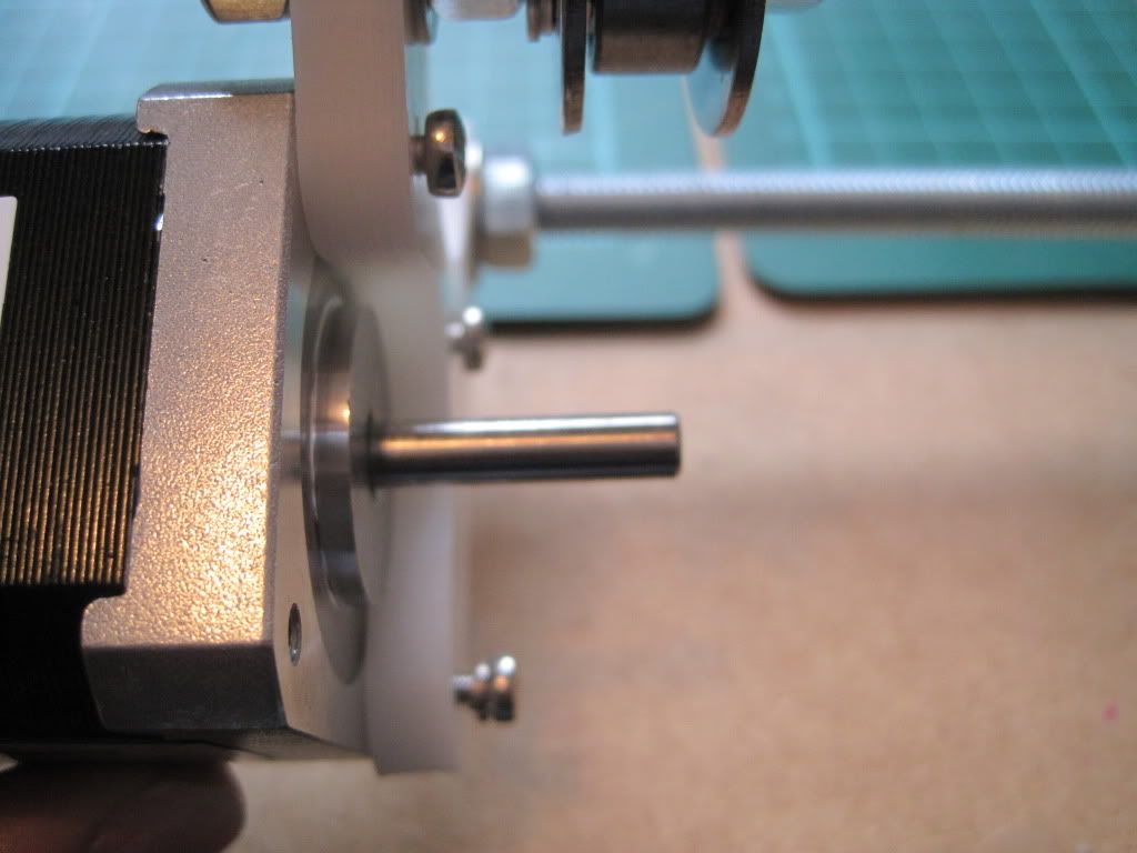
I got back to work by attaching the Y axis stepper motor. We don't carry M3 by 10mm screws at work, so I got 12mm long ones instead. I knew that the motor screw holes bottom out and that 12mm would be too long, so I got some spring washers to take up the slack.

The screws fully seated - you can see the slack caused by them being too long. The bottom screw has the spring washer fitted.

Next I fitted the pulley to the motor shaft. I had gotten a couple of pointy grub screws, thinking that flat ended ones wouldn't grip the shaft well, but hadn't looked at the screws Nophead had supplied. These turned out to be pointed as well, so I kept them (thanks Nophead!). I aligned the pulley with the bearing and tightened it into the shaft before checking that it gripped well and didn't turn. At the same tie, I moved the Y axis bearings closer to the middle of the frame. They were a way off to one side, and I was worried about off-centre forces affecting the movement of the axis. I brought them as close to the centre as possible.


I realised I had forgotten the plain washers behind the spring washers. I went back and fitted them.

I wrapped the Y axis belt (the shorter of the 2 supplied) around the bearings and lined it up over the lower sheet. I marked where it lay on the sheet, and started to carefully remove the sheet form the Y axis smooth rods. Then, disaster! - the bushings came off. Whilst the superglue had done a good job of holding it while it was flat, it cracked when I started to move it vertically.


I took the sheet off completely and used the opportunity to mark up the clamp holes and drill them.


I glued the lower tray down to the bushings again, and will continue with the fitting and tensioning of the belt when the glue is dry. The only good thing to come of this is that the movement seems a little smoother now I've reglued it. Perhaps the bushings were misaligned when I fitted them initially.

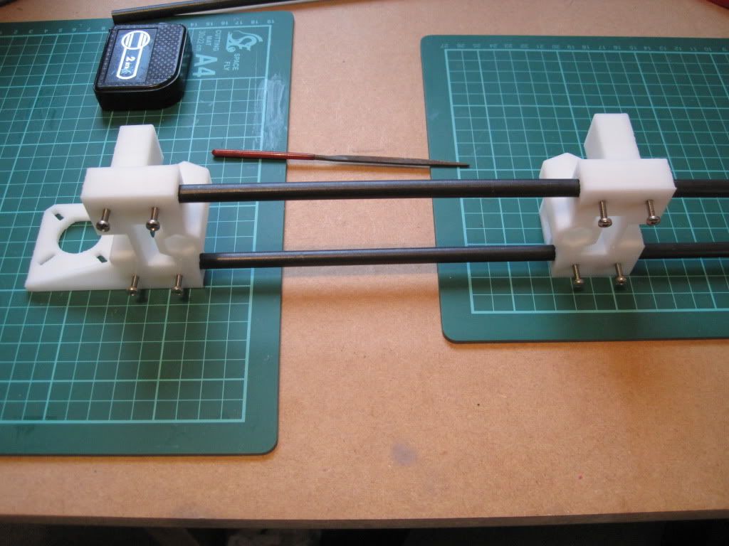
Whilst waiting for the glue to dry, I figured I'd make a start on the X axis. Here are the ends:


The holes are all the right size, so no need to drill anything out. I fitted the nuts into the traps, which was a little fiddly. I used the end of a file to make them lie flat when needed:


I fitted M3x12 screws into the nuts (again lacking in 10s). These seem excessive (although they may have something important to do later), and I think that M3x8 or even 6 would be better.


The visual instructions say to lay the parts out 500mm apart, but for the suggested X axis smooth rod length of 420mm this was too far:


Anyhow, I fitted the X ends to the rods, and tightened the screws:


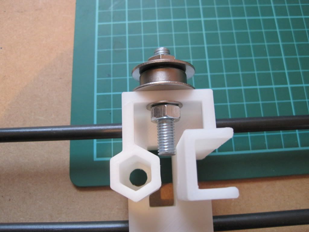
I built the X end idler bearing onto a 50mm piece of threaded rod, and fitted it, and that's the X axis done for now:


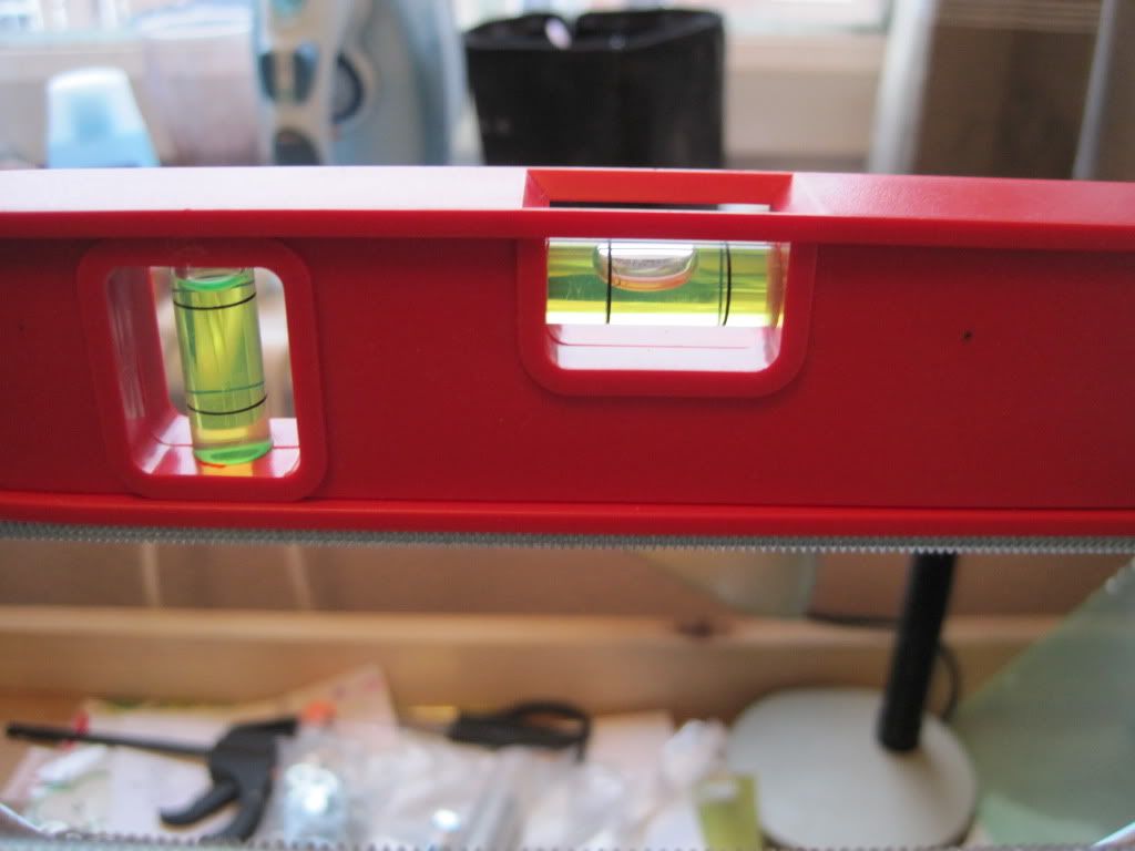
The next job is to level the printer. Mine was a bit wonky:


A pair of plastic rules provided the bulk of the adjustment required, with folded post-it notes providing the fine-tuning.


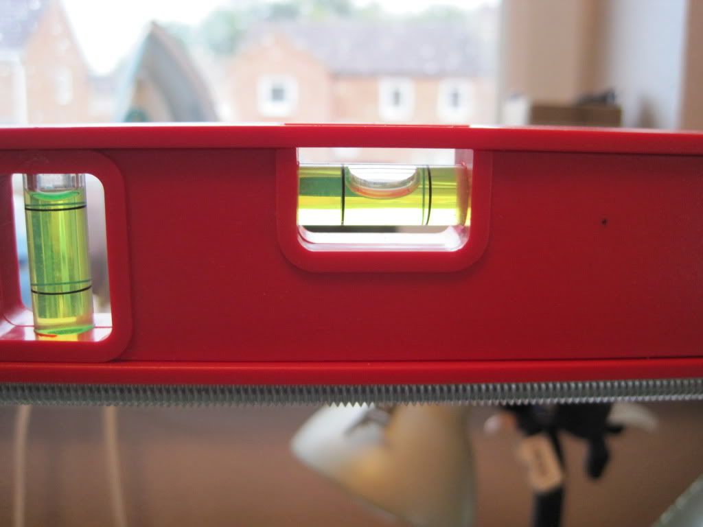
After adjustment - nice and level.

I have a snap-on adjustable foot in mind as one of my first upgrades....

The preliminary adjustment of the Z rod fixings went well, and I moved on to the upper fixings. I fitted up M3x25 screws as suggested in the assembly instructions, but found they were too long. I hadn't read far enough ahead to spot the note about this! I was on the brink of turning the screws around and trying them in reverse, when I looked back at my parts list. I realised I had gotten the correct amount of 20mm screws, so I replaced the 25s and the rod restraints now fit well:

I test fitted a motor to make sure the screw threads didn't protrude too far - they don't.
The last part of this evening was spent fitting the z rods and checking them for verticality. It was a slightly painstaking process, but well worth taking time over.


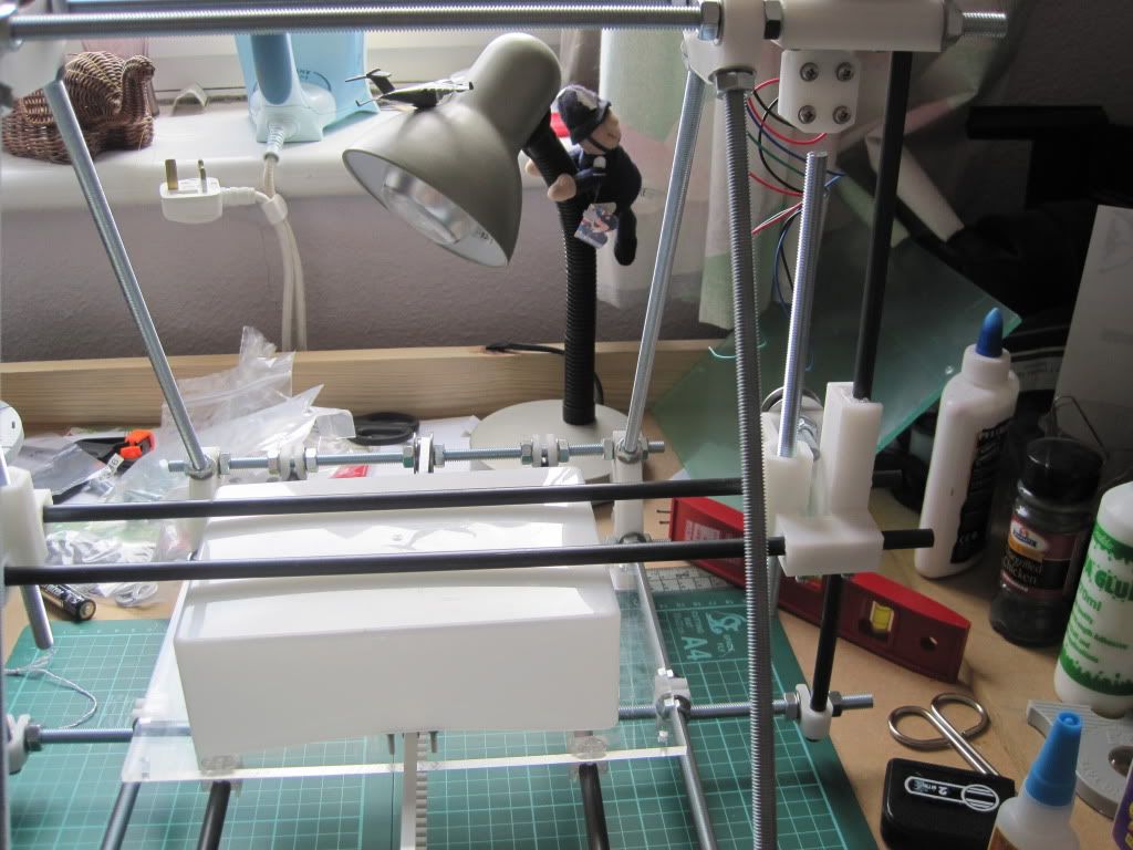
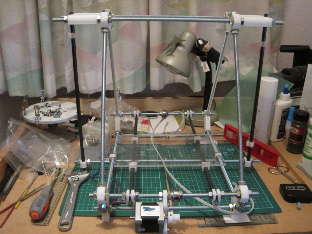
So here is the machine after all of today's exertions. I'll let the glue dry overnight, and hopefully tomorrow will see the mounting of the X axis.


Next up: X's, Z's and leadscrews!