Showing posts with label spring. Show all posts

Sunday, 16 October 2011

Chapter 20 - In which problems are rectified, and I make a temperature sensor the professional way

Its been a while since my last post. This is due to having had a week away in Scotland, but also due to progress being slow. I have however made some progress.

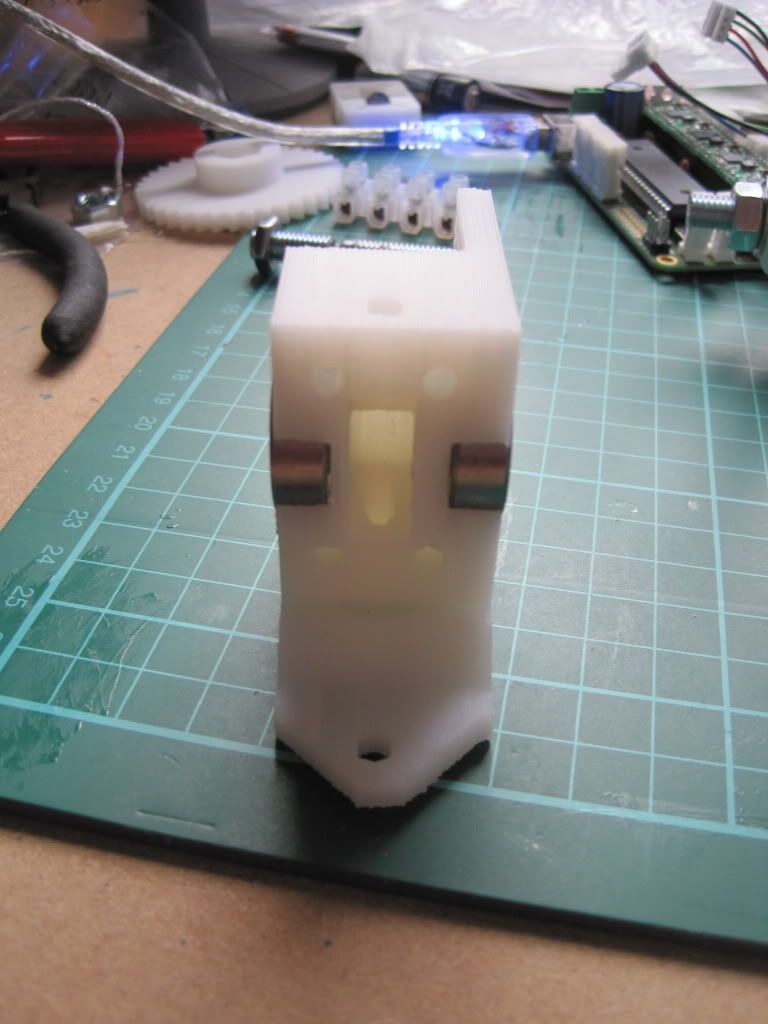
Firstly I changed the angle of the X-axis endstop. I had test-fitted the extruder body, and found the endstop was in the way. There is a conveniently provided little square protrusion on the side of the carriage, and the contact of the realigned endstop sits nicely on it.

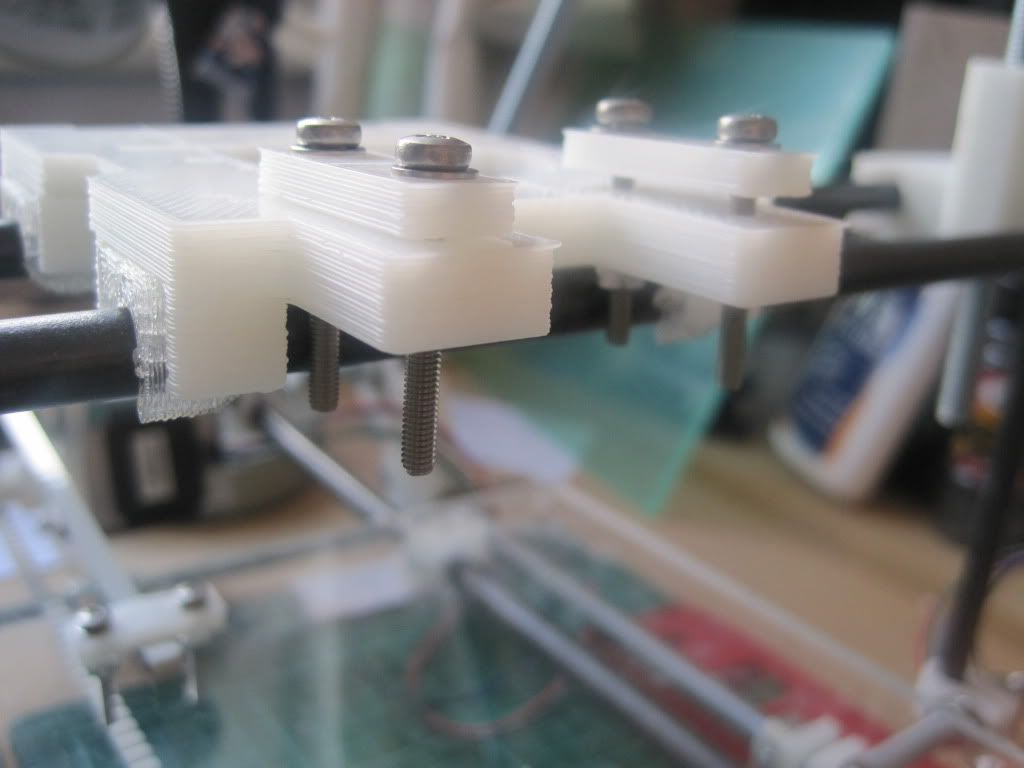
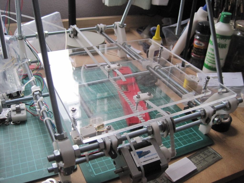
I then proceeded to fit the print bed. I had spotted this post on the forum, and decided to make the upgrade now rather than later. I had also got lots of peg springs just waiting for a use. I have used countersunk screws to mount the bed, but only because they were the only ones I could get with the correct length. There are washers under the heads to prevent the screws pulling into the bed and cracking it.
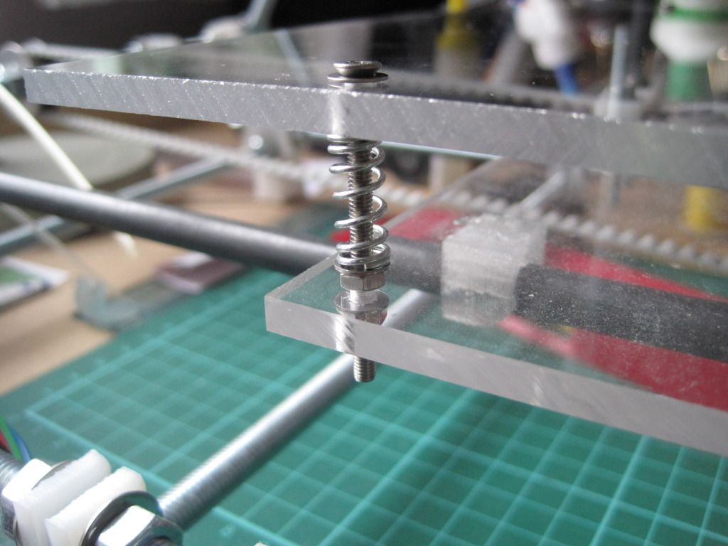


The bed is fairly level as it is, but I may tighten up the nuts to compress the springs, making the bed firmer and less prone to wobble. This has the added advantage of giving some extra Z height.


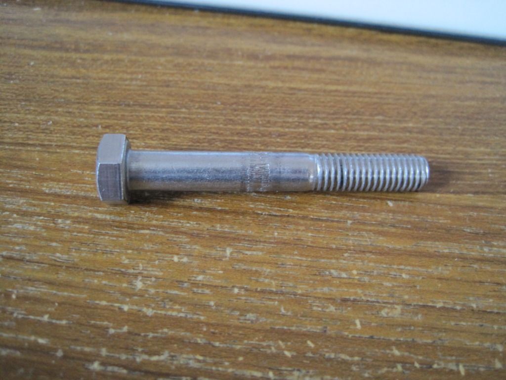
I had ordered some replacement bolts to hobb, as the previous one was too narrow. Once they turned up, I spent an evening in the garage attempting to hobb one of them. It was much harder going than the previous bolt - maybe these are made of something harder? I was also trying to hobb with an M6 tap as opposed to an M3, to give bigger teeth on the bolt. I just couldn't get it to cut the teeth correctly, and it left an un-cut section in the middle of the bolt. I ended up getting very frustrated with it, and walked away trying to decide how to go about making one properly.

I came back to it a week or so later, and had a proper look in the daylight. The hobbing down one side looked pretty good, and fairly even. I figured that I could probably space the bolt such that the good section was doing the driving.


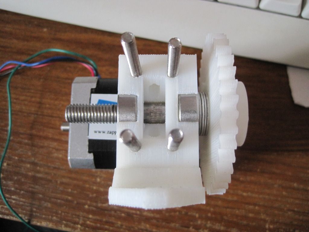
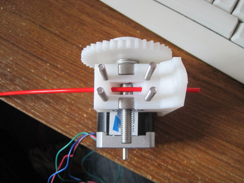
I put the extruder back together, and was pleasantly surprised to find that the good section was in the correct place already. Better than that, it had enough grip to drive feedstock without the idler in place! Whilst working on the extruder, I also moved the motor and fitted the bolts that will mount the extruder to the X-carriage. I reassembled the extruder and idler, and repositioned the motor to get the best interface between the gears.

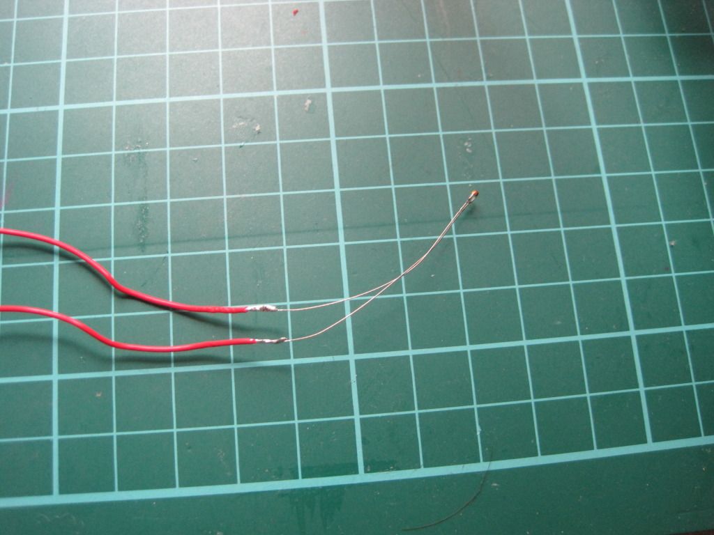
I also had the time to make up the hot-end temperature sensor. I constructed this in a similar manner to how professional temperature sensors are made. Firstly I soldered the ends to the stripped ends of the PTFE wire:


I then used high-temperature heat-shrink sleeving to insulate one leg, all the way from the small joint at the thermistor head to past the solder join:
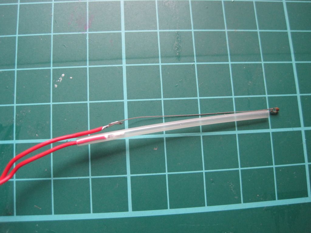


I shrunk the sleeving with the kind help of my girlfriend and her crafting hot air gun:
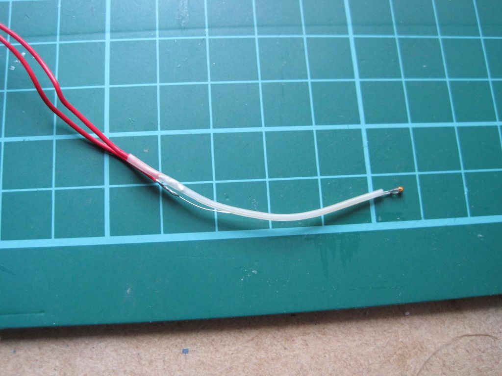


I then used a larger diameter piece of the same sleeving to cover the entire assembly, from a point past the thermistor head to past the remaining soldered joint.
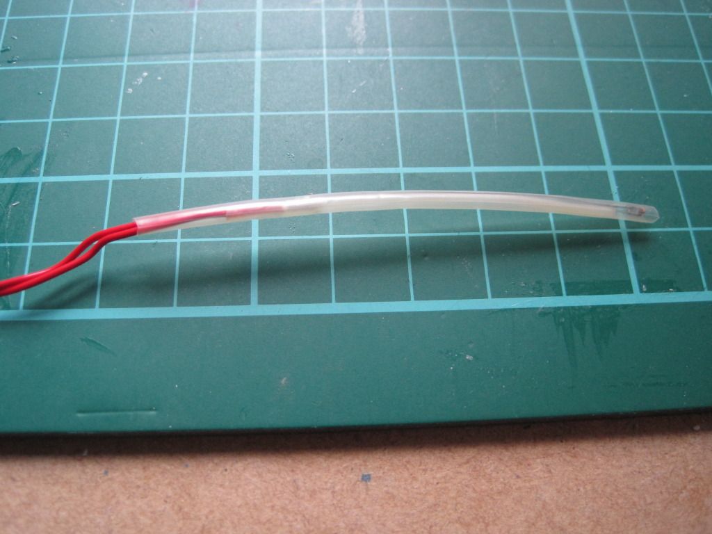
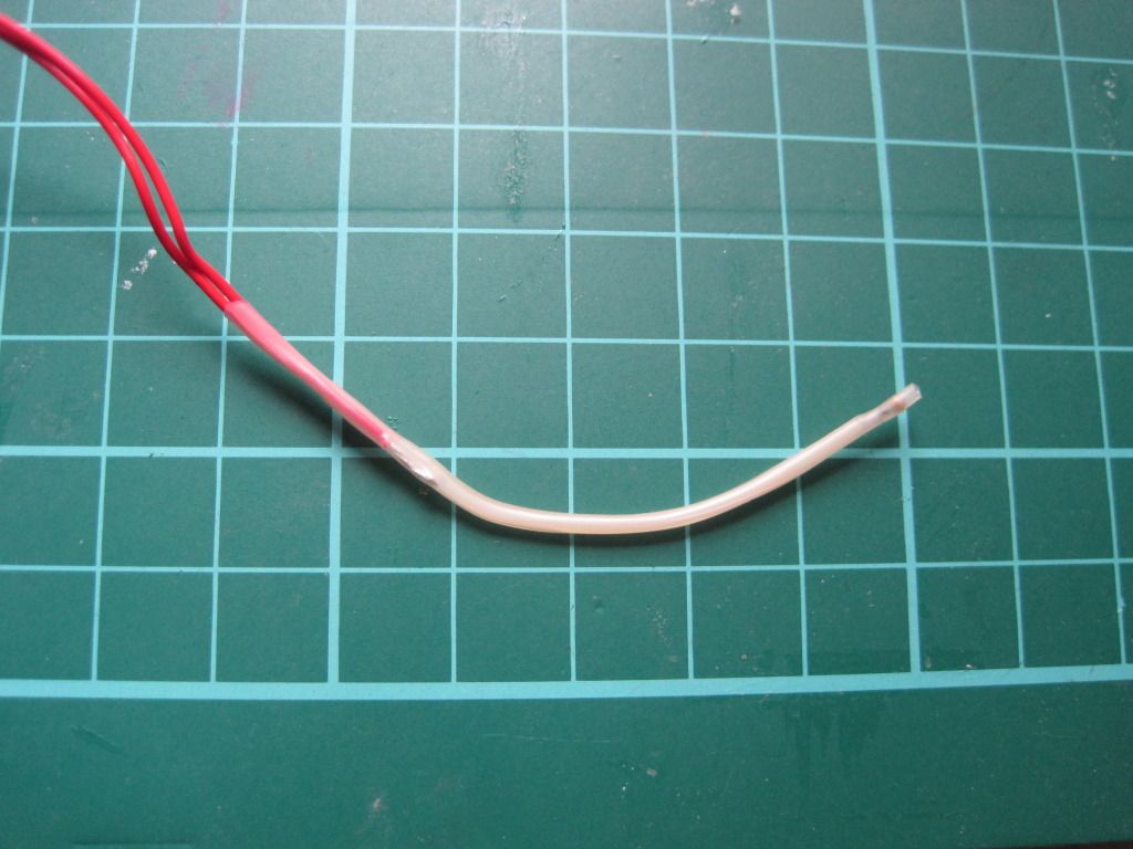


Lastly I trimmed the overhanging sleeving close to the bead. This assembly method should provide a robust and short circuit-free sensor for the hot end.

And Thats all the I've managed to achieve. Next up: The long-awaited hot-end post?

Tuesday, 27 September 2011

Chapter 18 - In which my alternate spring source is validated

One quiet Sunday, I sat down to build my extruder. I had already hobbed the bolt, and so now only needed to build up the extruder body.

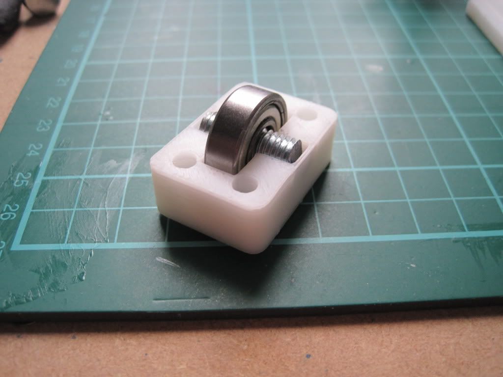
I had a little trouble fitting the bearings into the extruder body, but a little work with a file ensured that they sat flush:


I had a peice of threaded rod left over from cutting the frame bars down, so I cut it to 50mm and used it to mount the idler bearing. The bearing seems a little loose though, so I may have to change it out in the future.


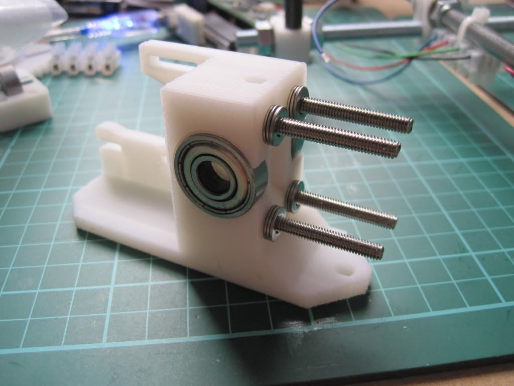
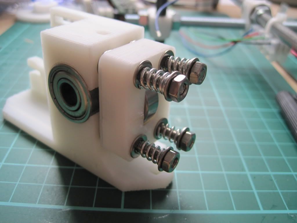
I fitted M4 by 50mm bolts through the extruder body, and fitted a pair of washers to each one. I had to file out the screw holes a little to make the bolts fit.


I fitted the idler block over the bolts - this was harder that I had thought it would be, due to having to keep the block square or the bolts would bind up.

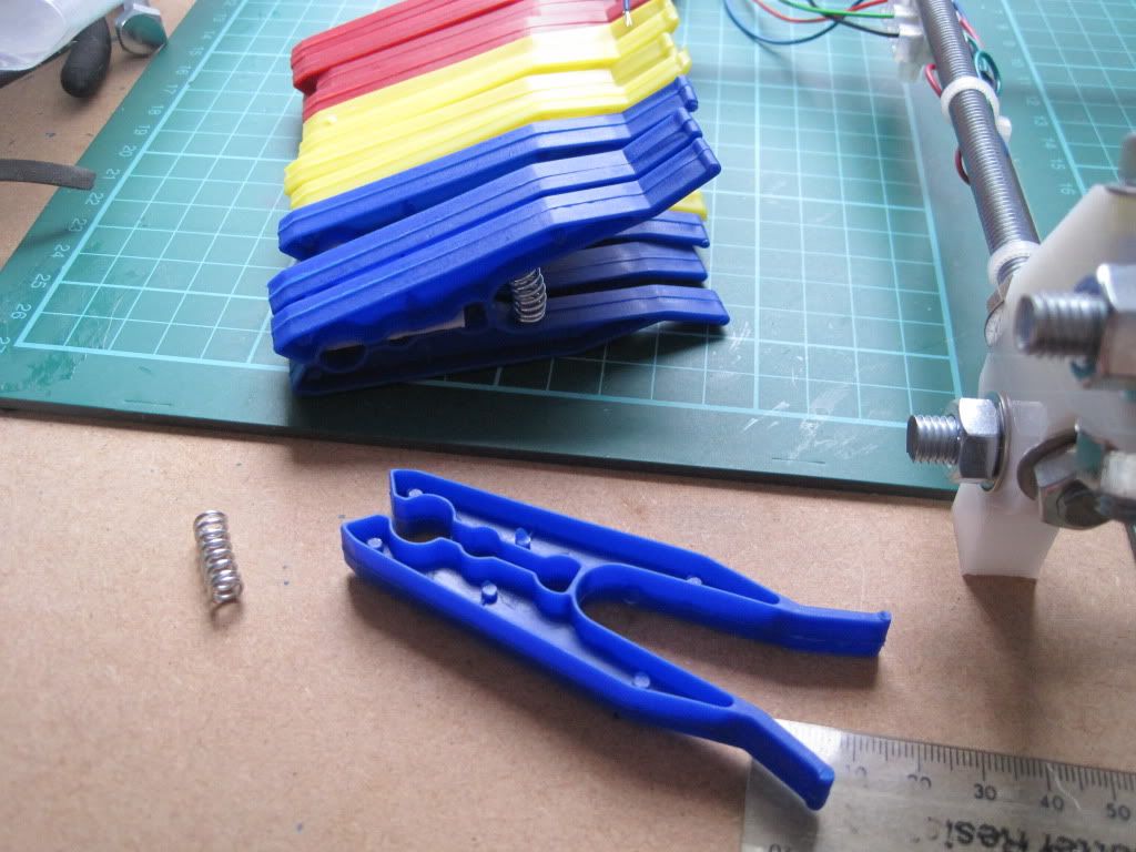
Now, time for the all important springs. As I mentioned here, I had found a source of springs in a certain shape of clothes peg. I had ordered some after scouring ebay for the right type. Unfortunately when they arrived they were the traditional, sideways-action spring type. I got in touch with the company, whoi were able to find some of the kind their listing showed. Lesson learned by me - some photos on ebay are for illustrative purposes only. Once I had the new, correct, pegs in hand, I set about de-springing them.


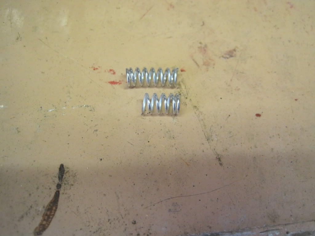
Having removed 4 springs, I was faced with another problem - they are too long for the bolts. After failing to compress them enough to get a nut onto the thread, I took them to the garage and took a hacksaw to them.  I cut them down to just the right length to allow them to be fastened on, with only a little compression.


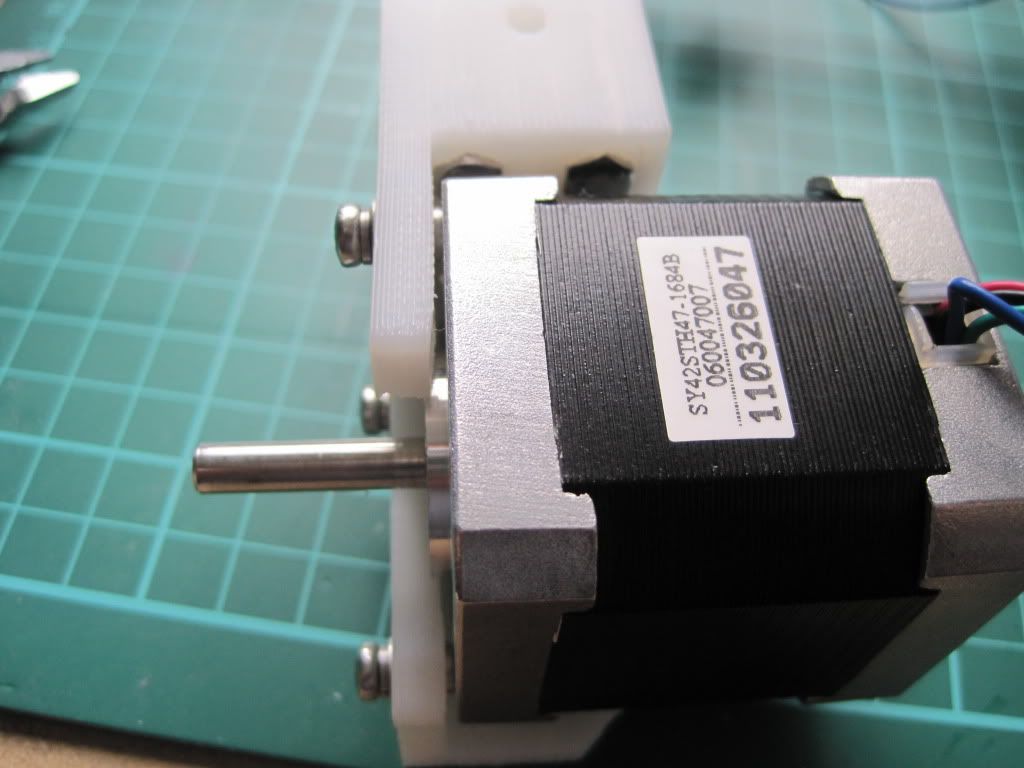
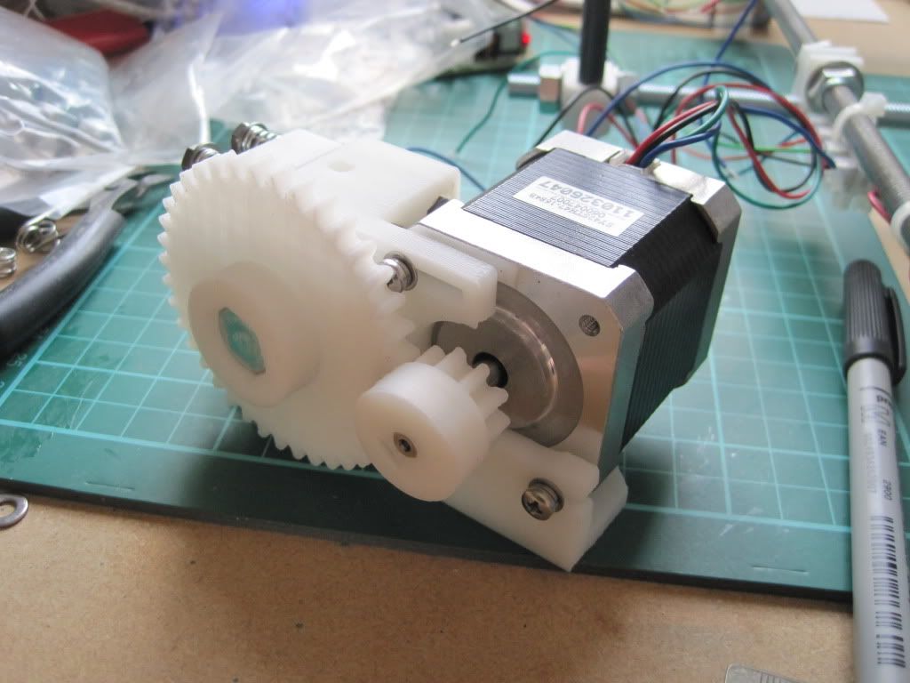
The motor mount on the extruder is thinner then that of the Y axis, so I though I could use the same trick of doubling-up the washers as I did on the x-end-motor. However, This made the Screw heads stick out too far, and they interfered with the gears. I opted for the solution below, with one set of spring washers between the motor and the extruder, and the other next to the screw heads:


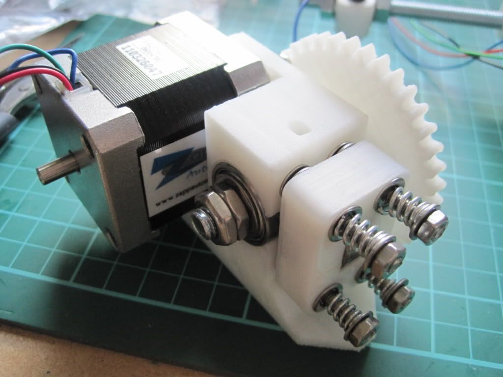
I fitted up the hobbed bot and large gear. I had to use 4 M8 washers to space the bolt correctly, because the hobbing had drifted to one side.


I had used a couple of M8 halfnuts that I found to hold the hobbed bolt in place, but have subsequently moved to one half nut and one full nut as I had problems getting the tension right and the locking tight enough.

Because of the extra washers spacing the big gear, I had to mount the small gear in reverse. This is actually suggested in some of the instructions, and won't cause any trouble due to the grub screw still being securely on the shaft.


Next up: talking to the machine

Thursday, 25 August 2011

Chapter 12 - In which I finish the X axis, and have a good idea

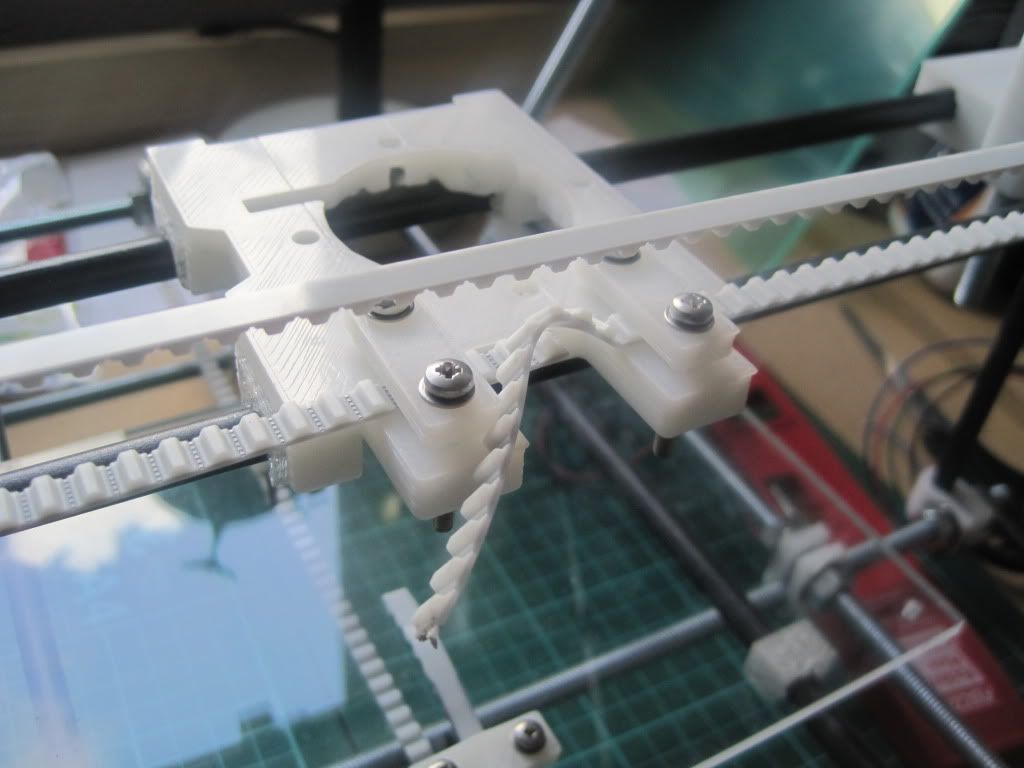
I wasn't happy with how the X carriage was travelling, and so I loosened off the smooth rods and rotated them (one at a time) until the carriage moved much more freely. I then fitted the belt clamps.


As you can see, the suggested M3 by 25mm screws are very long. In fact the back pair are so long they interfere with the smooth rods, and the carriage binds (this is probably due to how the carriage sits on its bushings). I replaced the rear screws with a pair of 12mm ones taken from the X axis ends (which were too long in the X ends anyway, and were replaced with some M3x6 screws I had found in a draw earlier).

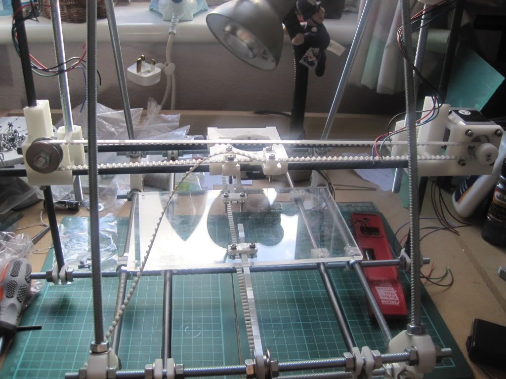
I fitted the X belt in the same orientation as the Y, namely with the teeth facing downwards in the clamps. It was only when I threaded the rest of the belt around the idler and back that I noticed that it was wrong - the teeth should face upwards, and the belt travel above the carriage rather than under it. I reassembled it and tightened everything up. The carriage now moves very smoothly, seemingly with no backlash.


I cut the belt off leaving a little for adjustment later if needed.


And that's as far as I can go today. Next I will build the electronics, but I need a PSU before we have any movement. I can also build the extruder once I get a few more bits delivered.

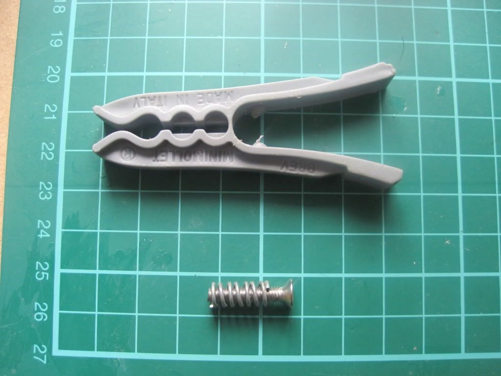
Whilst in the draw that yielded the earlier M3x6 screws, I also found the solution to the spring problem. I had previously been unable to find a cheap source for the springs needed to tension Wade's idler bearing in the extruder. I found this clothes peg, the spring from which is perfect:


I scoured ebay and picked up a pack of 24 for £2.50 - that's just over 10 pence each, a marked improvement on the £1 or £2 each I had previously seen springs going for.

Next up: Electronics build