So I left you last time with a question - would me new steel-bodied extruder design print?
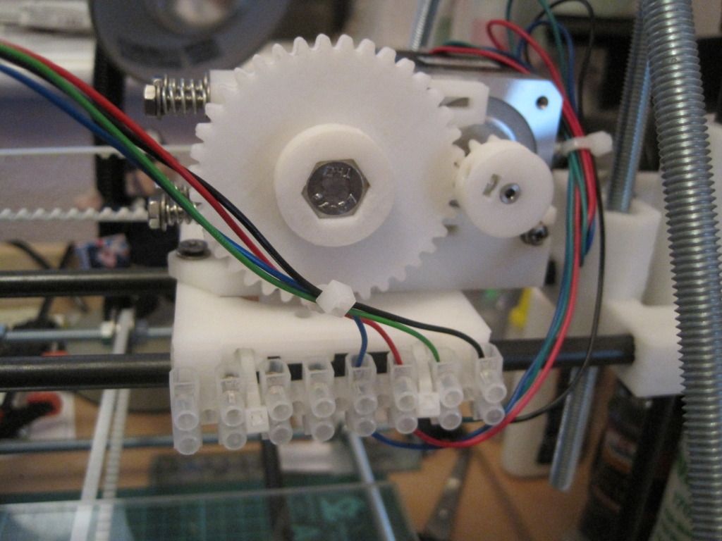
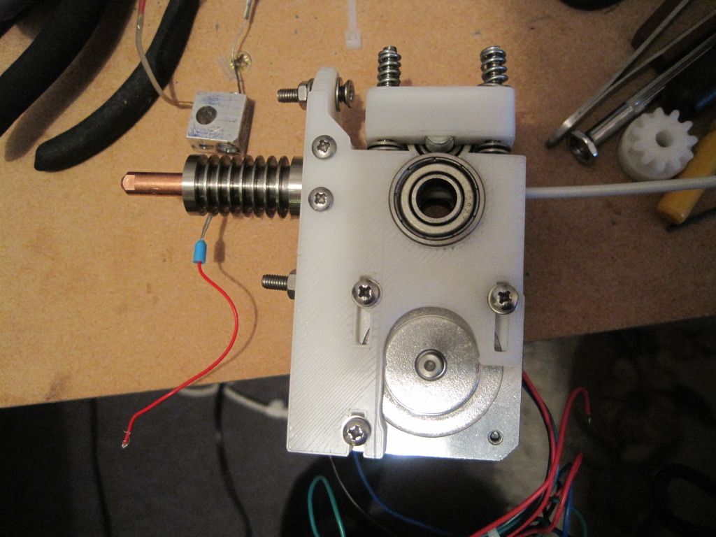
Well, I assembled it and mounted it to my extruder body:
I knew that this design would need some active cooling - stainless is conductive afterall, and so I mounted a 40mm computer fan on the carriage to blow air over the fins. I powered this from one of the sanguinololu's 12v plugs.
I loaded a 20mm cube into sfact on pronterface, and sliced at 0.3mm layers. I warmed up the hotend to 185, and pressed "print" - a scary moment, as it handed control of the machine over to the software and it started moving!
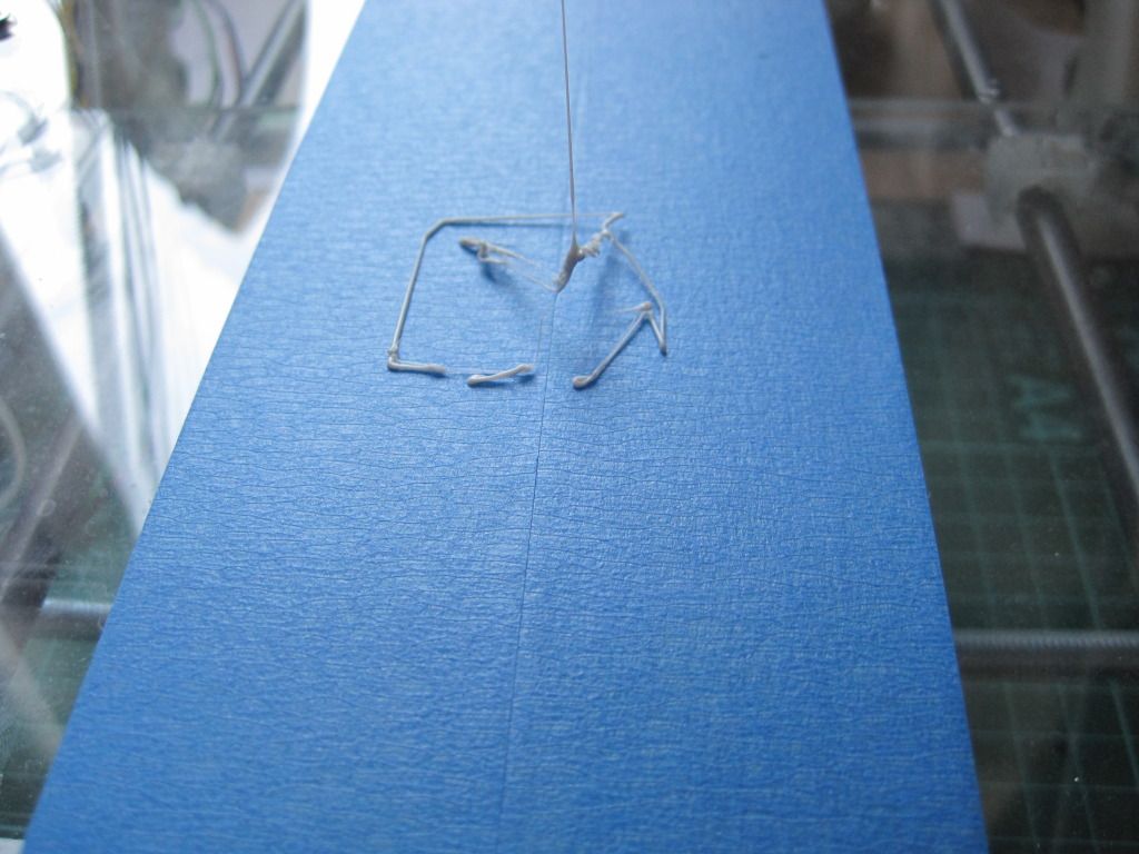
I got part of a raft, and not much more. It looked as if the extruder had jammed, and no matter what I tried I couldn't get it to move again. Finding the cause of the jam this time was fairly easy - I had put the fan on backwards! The heat had conducted up the barrel and without cooling had caused a jam.
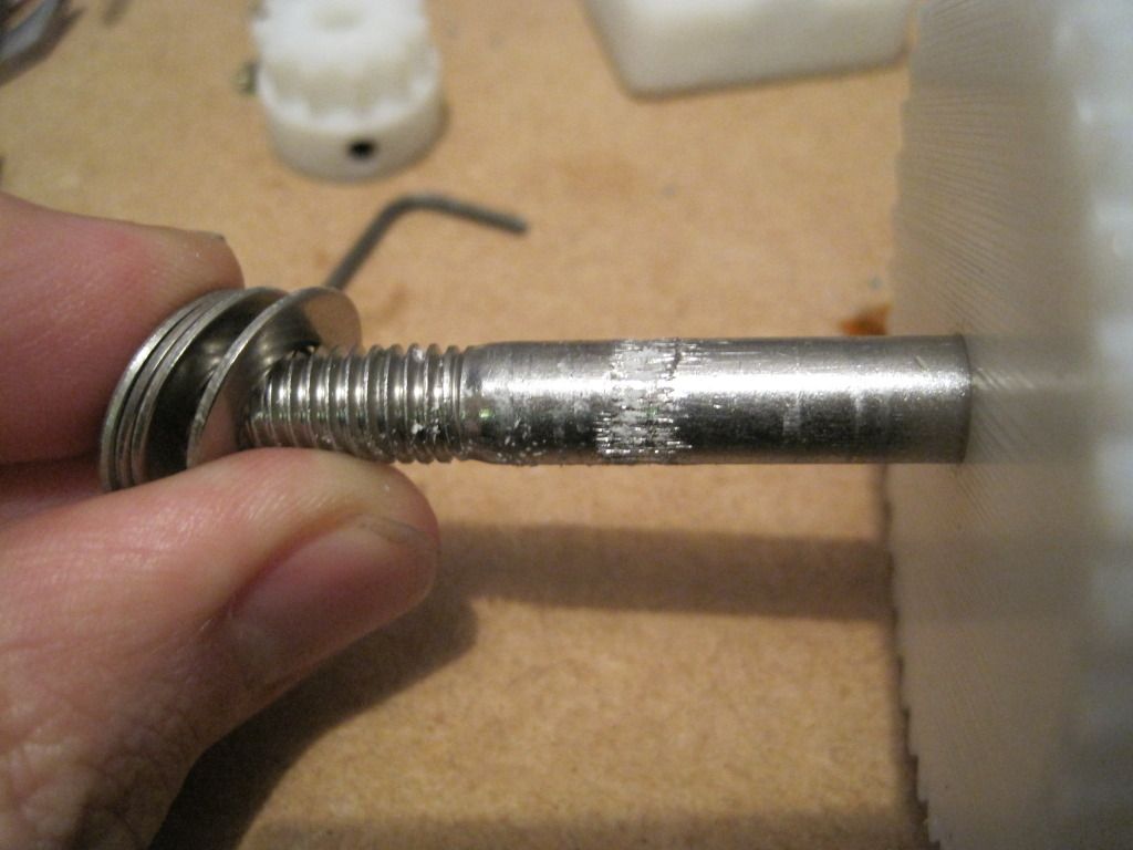
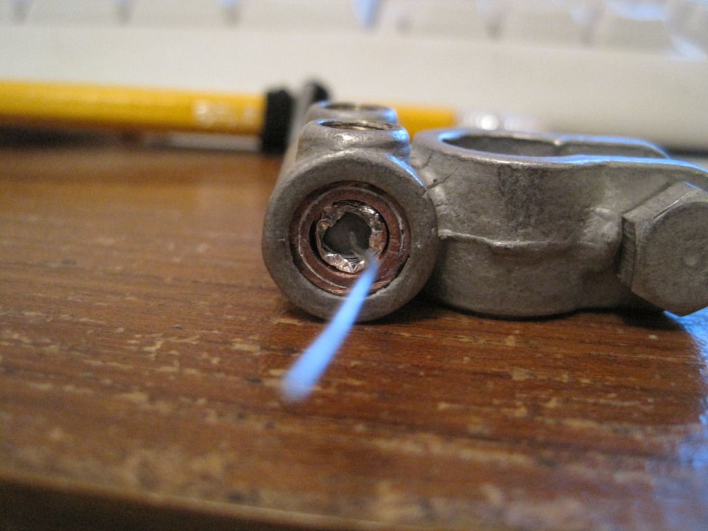
I stripped the entire assembly down. There was PLA dust in the hobbing on the bolt:
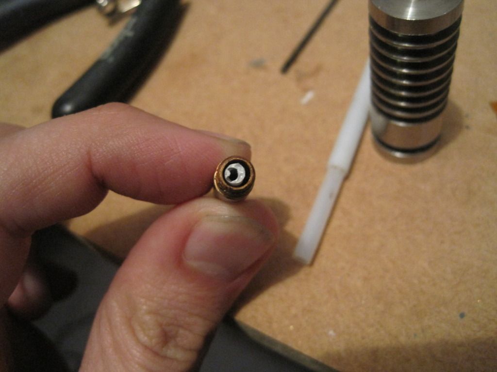
There was also material stuck in the PTFE, and in the nozzle:
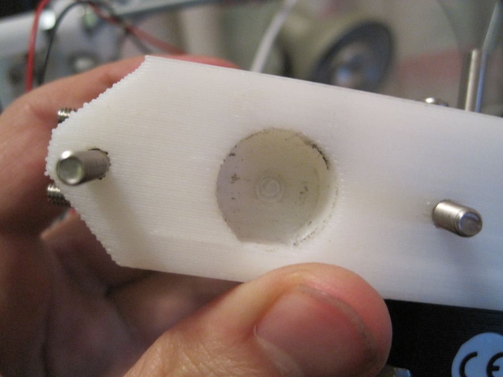
This is where the jam occurred - right at the top of the barrier, as the feedstock enters the stainless.
The feedstock had expanded as it got hot, and jammed up. I had to use SERIOUS force to clear it - it had expanded some 20 or 30%!
I cleared out all the dust and jammed, overheated material and reassembled the entire thing. I reversed the direction of the fan, and tried to print again........
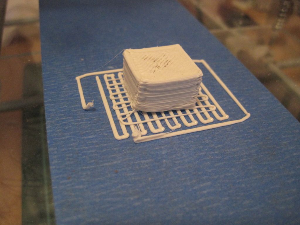
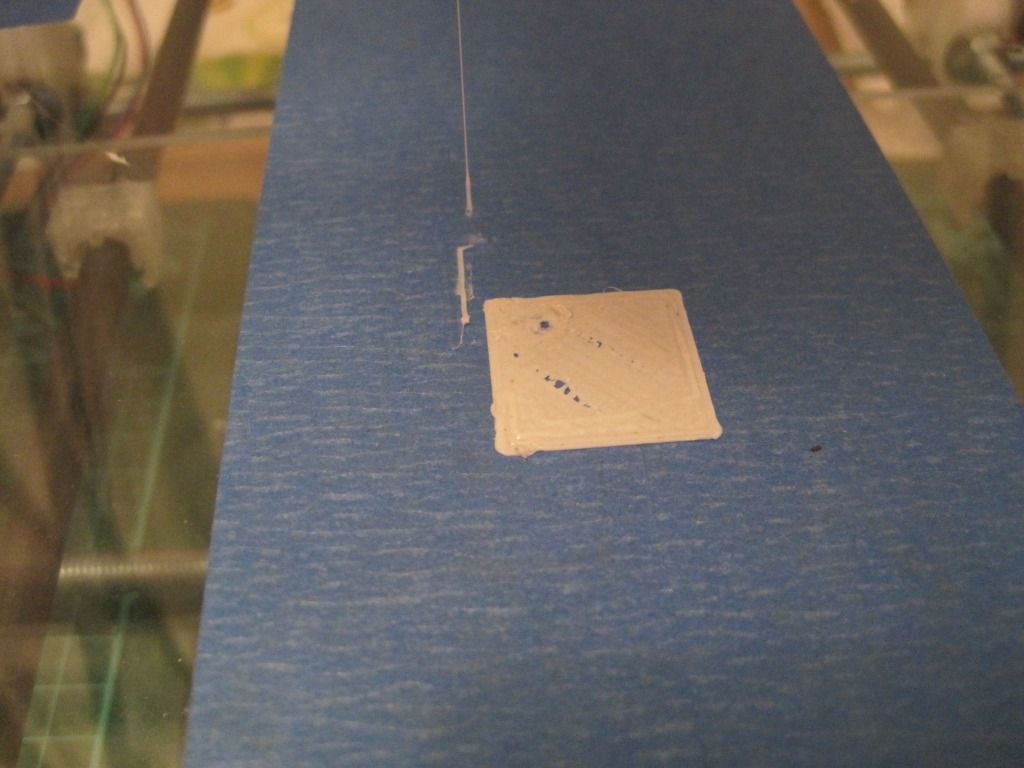
Finally, an object!
Sure its not perfect (the skirt isn't complete, and it is seriously undersized in height), but it IS an object, and I printed it!!
It was shortly after this high point that the printer went on it's holidays to the garage - we needed the workbench space for making Christmas cards. When it comes back, the fun will really start.
Next up: more printing!
A Blog in which I describe my build of a Prusa reprap machine, to print objects in 3D.
Thursday, 16 February 2012
Saturday, 7 January 2012
Chapter 24 - In which I design and build a new hot end
Happy new year! I'm still behind with my blog postings (no surprises there...), but am trying to catch up. One of the biggest and most significant event in the last few months has been the design and build of my new extruder hot end.
In my last post, I described how my PTFE barriers had all failed. With that in mind, I set about designing something that would be incapable of failing as the PTFE had done. I wanted to steer away from PEEK due to the cost, and the fact that the operating temperature range is only slightly above that of PTFE - I know that with my luck I'd start to push nozzles out of it.
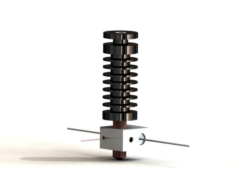
Inspired by one of Nophead's designs, I chose to make the new thermal barrier out of stainless steel. Although stainless is considered quite a poor thermal conductor (amongst metals) it was still going to get pretty hot when the nozzle is at 200C. I designed the barrier to be made from 16mm bar stock so it will fit in the body of wades extruder, with a set of cooling fins along the body. The high temperature of the hot end, the fact that the barrier is only 40mm long, and the relatively large mass of the barrier means that I will have to actively cool it to prevent the feedstock from swelling and jamming. A small fan will blow across the fins to remove the heat.
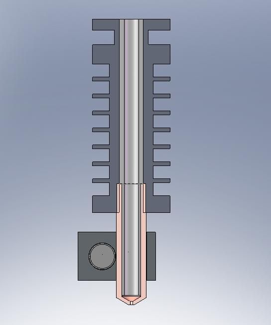
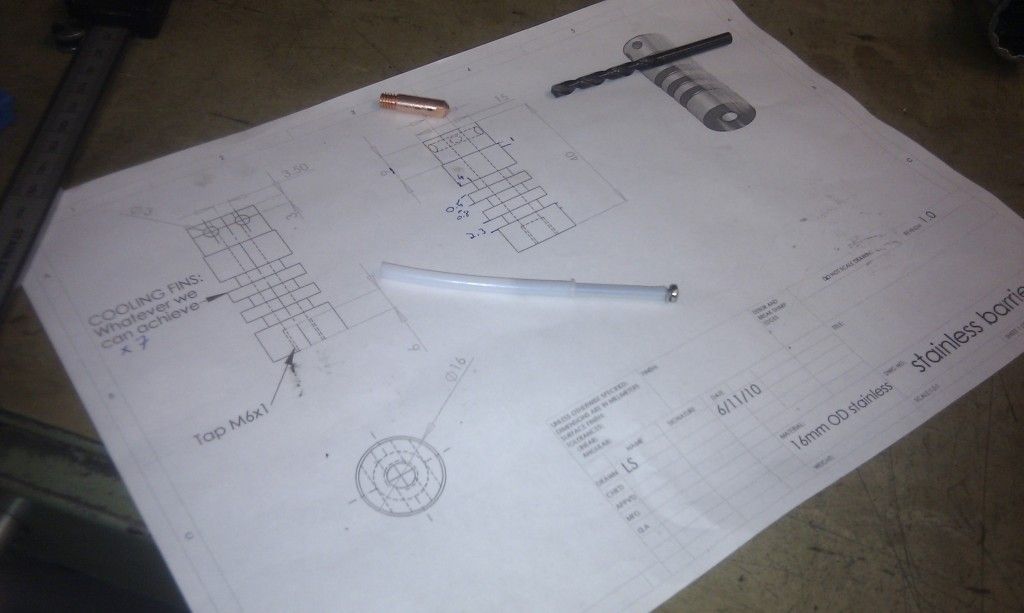
To prevent jams at the transition between the barrier and the nozzle, I will be using a PTFE liner. I had considered using sleeving, but eventually settled on some penumatics pipe (ebay again - 5mm outside diameter, 3mm internal diameter). This would run down the inside of the barrel and nozzle, right to the tip. This did create a problem though - in order to get the liner down into the nozzle (a MIG tip), I would have to reduce it's external diameter. The MIG tip's thread size is M6, which has a 5mm core diameter - if I drilled the MIG tip out to 5mm, there would be no thread left! I settled on a 4mm internal diameter for the tip, and a stepped liner design - 4mm in the nozzle and 5mm in the barrel.
In a last minute change-of-heart, I dropped the copper sleeves and car battery clamp of my earlier design. I would have to use machine tools to make the new barrier, so why not treat myself to a new heater block too? It is aluminium, 16x16x10mm, has a grub screw to hold the nozzle in place and has the thermistor positioned near the nozzle for a more accurate temperature reading.
Here is a render of the new design:
And here is a cutaway:
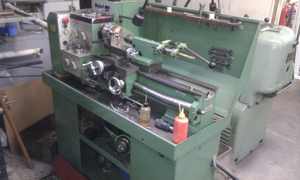
I borrowed the machine shop at work for the lathe- and drill-work. I want to thank Martin and Wesley for giving up their lunchtimes to help me!
We used a long M3 bolt down the inside of the PTFE pipe to keep it straight whist machining the reduced section:
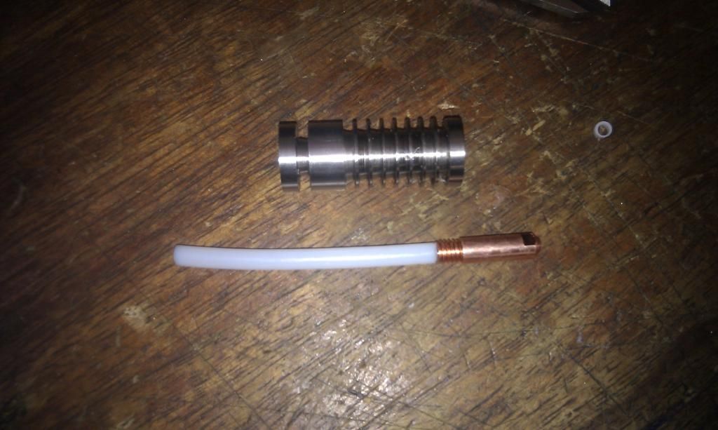
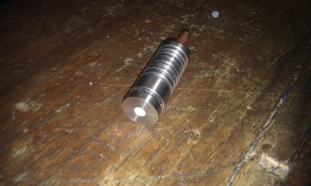
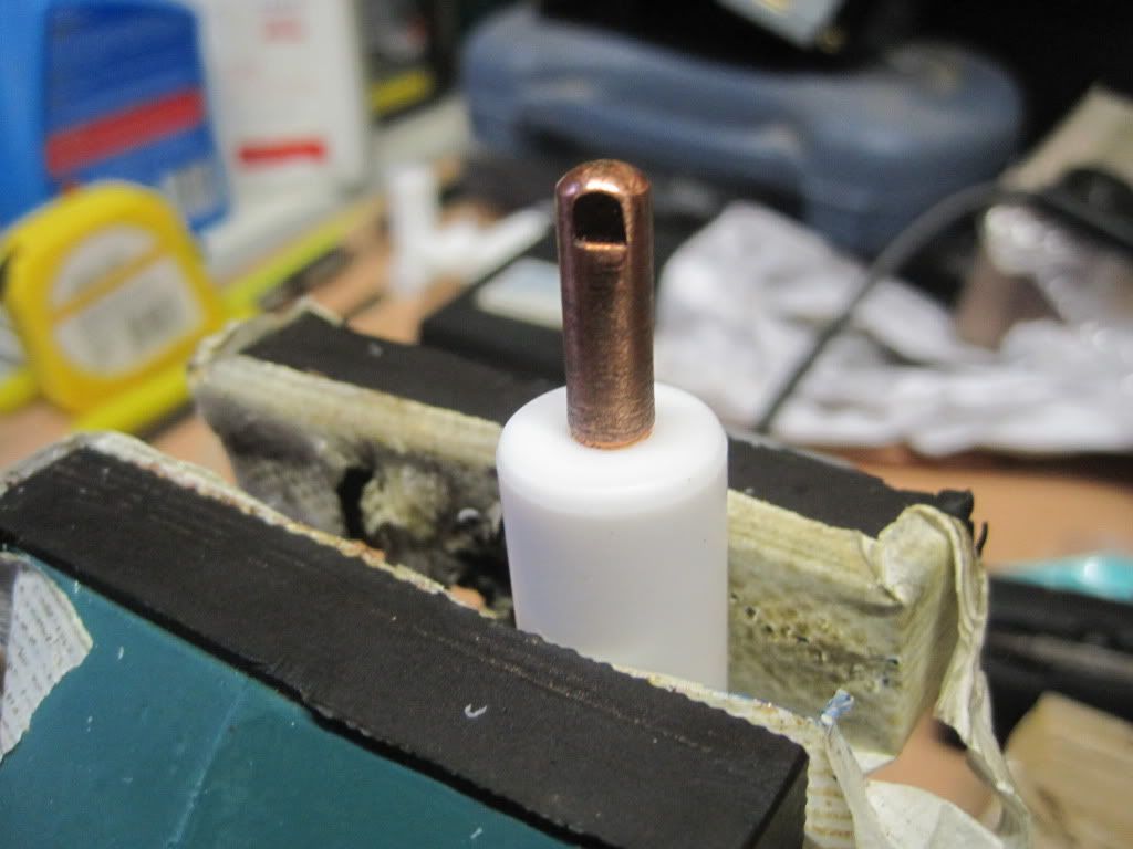
Lots of machining later, we have a completed barrier assembly:
The liner fits very snugly into the MIG tip, which screws nicely into the barrier. The liner sits flush with the top end of the barrier.
About the MIG tip itself - it has been drilled internally to 4mm as mentioned above, but has also had the outer bottom face machined back. We also reduced the nozzle hole size by tapping it with a hammer. While it's great that the hole is smaller, it also presents a problem - just how big is it? I guess I'll find out when I try to extrude.
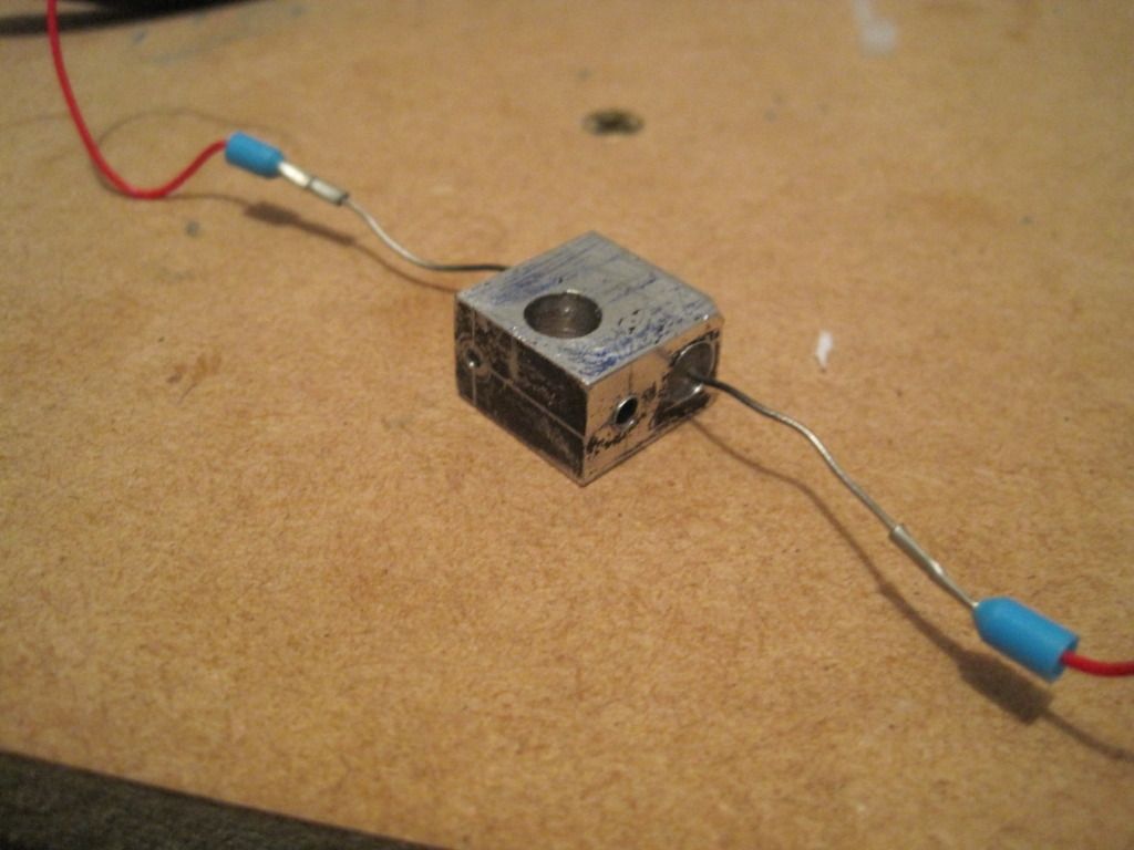
I forgot to take a photo of the new heater block being made, but here it is wired up with the resistor in place:
So, does it work? You'll have to wait till next time to find out...!
In my last post, I described how my PTFE barriers had all failed. With that in mind, I set about designing something that would be incapable of failing as the PTFE had done. I wanted to steer away from PEEK due to the cost, and the fact that the operating temperature range is only slightly above that of PTFE - I know that with my luck I'd start to push nozzles out of it.
Inspired by one of Nophead's designs, I chose to make the new thermal barrier out of stainless steel. Although stainless is considered quite a poor thermal conductor (amongst metals) it was still going to get pretty hot when the nozzle is at 200C. I designed the barrier to be made from 16mm bar stock so it will fit in the body of wades extruder, with a set of cooling fins along the body. The high temperature of the hot end, the fact that the barrier is only 40mm long, and the relatively large mass of the barrier means that I will have to actively cool it to prevent the feedstock from swelling and jamming. A small fan will blow across the fins to remove the heat.
To prevent jams at the transition between the barrier and the nozzle, I will be using a PTFE liner. I had considered using sleeving, but eventually settled on some penumatics pipe (ebay again - 5mm outside diameter, 3mm internal diameter). This would run down the inside of the barrel and nozzle, right to the tip. This did create a problem though - in order to get the liner down into the nozzle (a MIG tip), I would have to reduce it's external diameter. The MIG tip's thread size is M6, which has a 5mm core diameter - if I drilled the MIG tip out to 5mm, there would be no thread left! I settled on a 4mm internal diameter for the tip, and a stepped liner design - 4mm in the nozzle and 5mm in the barrel.
In a last minute change-of-heart, I dropped the copper sleeves and car battery clamp of my earlier design. I would have to use machine tools to make the new barrier, so why not treat myself to a new heater block too? It is aluminium, 16x16x10mm, has a grub screw to hold the nozzle in place and has the thermistor positioned near the nozzle for a more accurate temperature reading.
Here is a render of the new design:
And here is a cutaway:
I borrowed the machine shop at work for the lathe- and drill-work. I want to thank Martin and Wesley for giving up their lunchtimes to help me!
| No inverted drill here - a proper tool! |
| 5mm pipe on an early drawing for the barrier |
The liner fits very snugly into the MIG tip, which screws nicely into the barrier. The liner sits flush with the top end of the barrier.
About the MIG tip itself - it has been drilled internally to 4mm as mentioned above, but has also had the outer bottom face machined back. We also reduced the nozzle hole size by tapping it with a hammer. While it's great that the hole is smaller, it also presents a problem - just how big is it? I guess I'll find out when I try to extrude.
I forgot to take a photo of the new heater block being made, but here it is wired up with the resistor in place:
| I hope blue marker pen fumes aren't toxic... |
So, does it work? You'll have to wait till next time to find out...!
Sunday, 18 December 2011
Chapter 23 - In which I describe a catalogue of failures
Apologies for still being behind with the blog. Have been a bit busy recently, and as usual the "write-up" suffers.
I had fitted up the hotend, wired everything up and was good to go. I fired up Bernard, opened pronterface and set the temperature to 185 (the pronterface default for PLA). I loaded some feedstock into the extruder (not easy with all those springs) and ran it forwards until it was down in the barrel. I waited for the hotend to come up to temperature - this took a while, but I was expecting that as the mass of this hot end is fairly large.
Once at temperature, I tried to extrude. The result: a little dribble of filament, and nothing more. I tried again and this time was rewarded with the following:
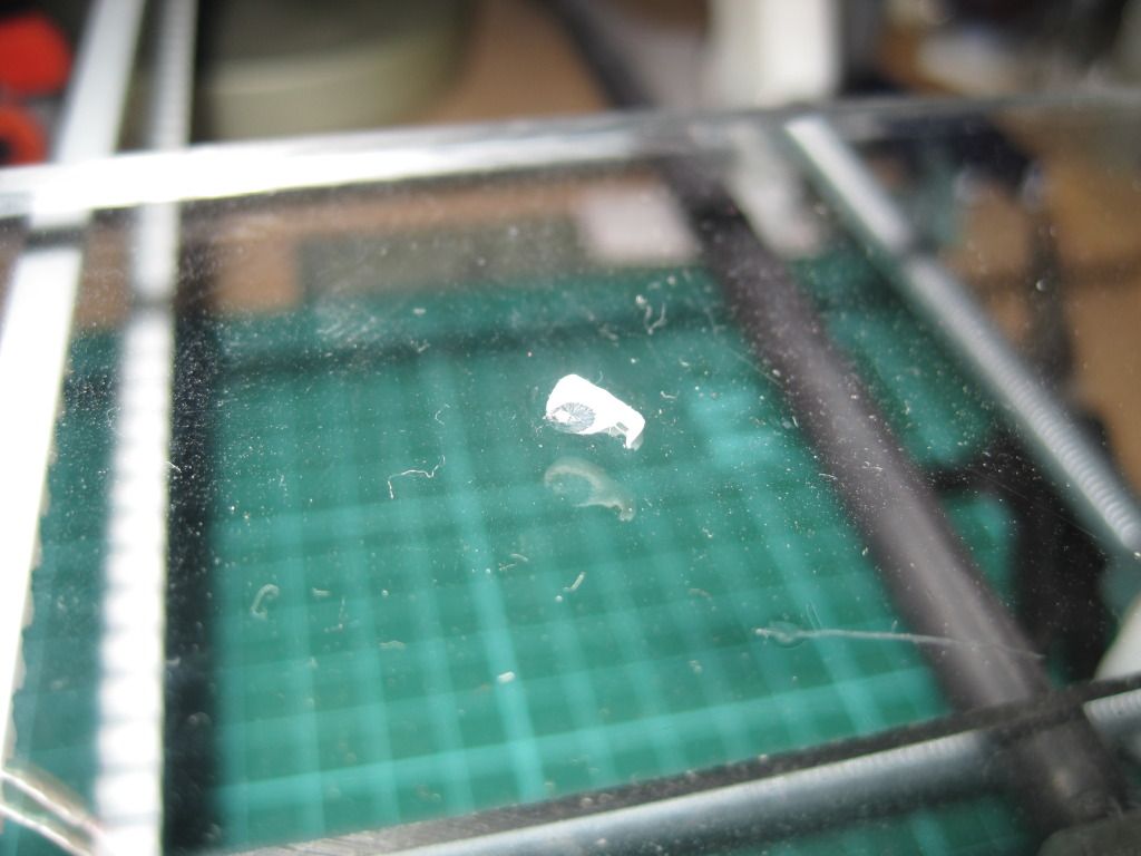
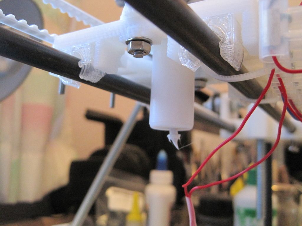
The PTFE had failed, and dropped the hotend, still at temperature, onto the bed. To be fair, I was expecting this to happen (apparently it always does) but had expected more printing time from it! I lifted the Z axis - this would let the hotend hang in mid air to cool down. It left this smear of PLA bonded to the acrylic:
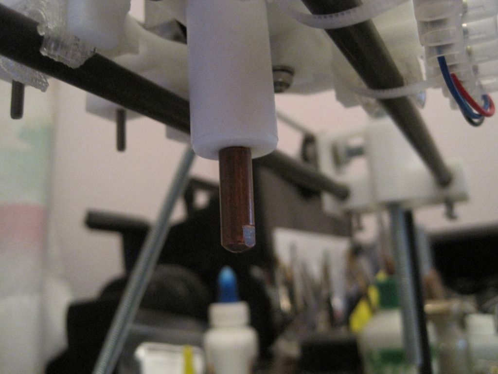
Here is the end of the feedstock:
Looks like the PLA may have expanded into a gap, and the resulting pressure forced the nozzle out of the PTFE. Interestingly another MIG tip screwed into the barrel ok, although it was a little loose at the start:
I put everything back together, optimistically hoping it would hold up OK. It didn't and rapidly failed again in the same way, which is fairly obvious now.
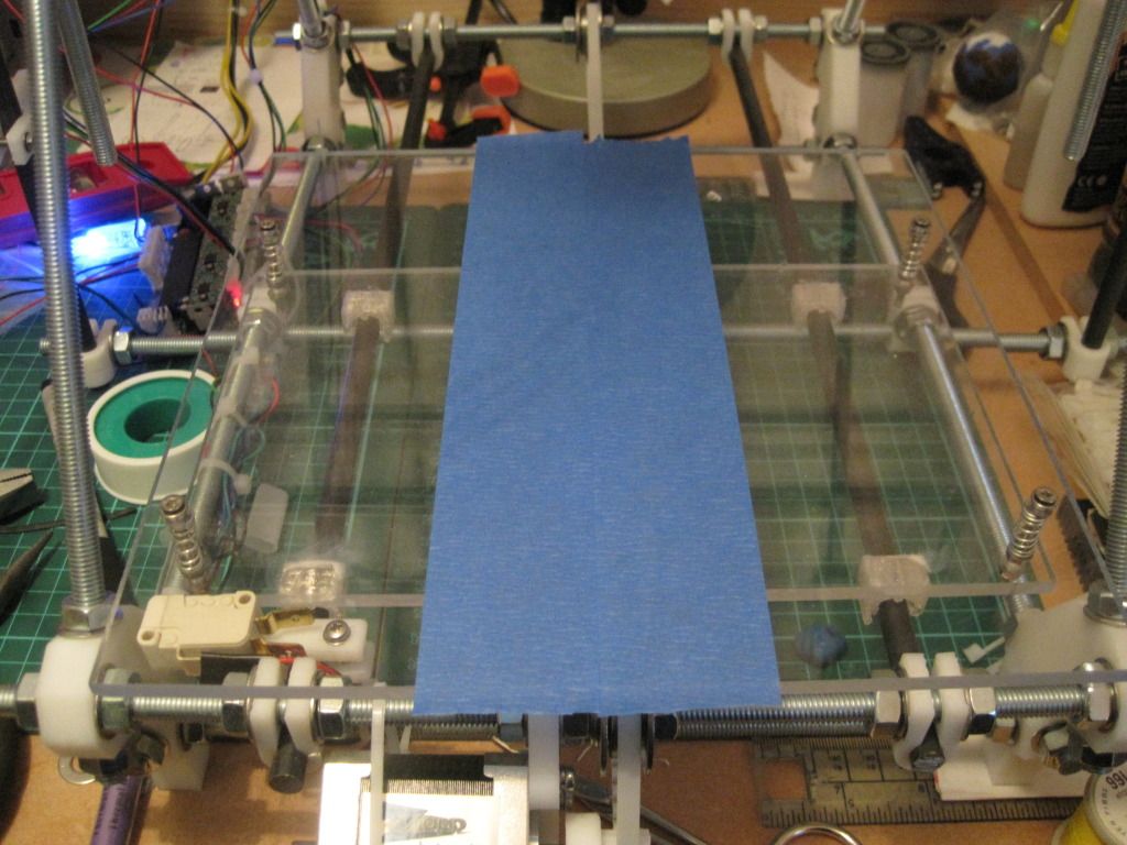
I took the extruder apart, and replaced the PTFE with one of the failed ones from before, that I had re-tapped to M6. This had a straight-through bore of 5mm. In anticipation of actually printing something, I added some blue tape to the printbed:
I realise now that it was pretty silly to use a large bore PTFE barrier, but I had been reading Nopheads thoughts on tapered expansion zones, and wondered if the same effect could be achieved with the larger bore.
Things actually looked pretty good for a few moments once it was up to temperature. It extruded filmant ok, and so I loaded up the STL for a 20mm cube and pressed the "print" button - a scary moment! I got the following, before another failure:
Predicatbly it failed again. what was interesting though was the feedstock in the barrel - instead of buckling, it had curled up as it warmed up and was pushed downwards, leading to a melt zone that was seemingly viable, albeit for a short period of time.
I repaired it again, with another for the failed barrels, and managed to get the following before the next failure:
Its square and kinda filled in - almost a success! It is only one and a half full layers, and the infill looks off, but that's to tweak another day.
Spurred on by this success, I went back to the garage and drilled and tapped the opposite end of one of the failed barriers. I drilled this one to 4.8mm (less than the recommended tapping size of 5mm) to try and get deeper threads, and I only tapped three quarters of the thread - I used a mig tip to thread-form the rest, such that it matched the thread exactly.
Surely this ultimate barrier wouldn't fail?
You'll have to wait till next time to find out, as I haven't downloaded the pictures yet!
I had fitted up the hotend, wired everything up and was good to go. I fired up Bernard, opened pronterface and set the temperature to 185 (the pronterface default for PLA). I loaded some feedstock into the extruder (not easy with all those springs) and ran it forwards until it was down in the barrel. I waited for the hotend to come up to temperature - this took a while, but I was expecting that as the mass of this hot end is fairly large.
Once at temperature, I tried to extrude. The result: a little dribble of filament, and nothing more. I tried again and this time was rewarded with the following:
The PTFE had failed, and dropped the hotend, still at temperature, onto the bed. To be fair, I was expecting this to happen (apparently it always does) but had expected more printing time from it! I lifted the Z axis - this would let the hotend hang in mid air to cool down. It left this smear of PLA bonded to the acrylic:
Here is the end of the feedstock:
Looks like the PLA may have expanded into a gap, and the resulting pressure forced the nozzle out of the PTFE. Interestingly another MIG tip screwed into the barrel ok, although it was a little loose at the start:
I put everything back together, optimistically hoping it would hold up OK. It didn't and rapidly failed again in the same way, which is fairly obvious now.
I took the extruder apart, and replaced the PTFE with one of the failed ones from before, that I had re-tapped to M6. This had a straight-through bore of 5mm. In anticipation of actually printing something, I added some blue tape to the printbed:
I realise now that it was pretty silly to use a large bore PTFE barrier, but I had been reading Nopheads thoughts on tapered expansion zones, and wondered if the same effect could be achieved with the larger bore.
Things actually looked pretty good for a few moments once it was up to temperature. It extruded filmant ok, and so I loaded up the STL for a 20mm cube and pressed the "print" button - a scary moment! I got the following, before another failure:
Predicatbly it failed again. what was interesting though was the feedstock in the barrel - instead of buckling, it had curled up as it warmed up and was pushed downwards, leading to a melt zone that was seemingly viable, albeit for a short period of time.
I repaired it again, with another for the failed barrels, and managed to get the following before the next failure:
Its square and kinda filled in - almost a success! It is only one and a half full layers, and the infill looks off, but that's to tweak another day.
Spurred on by this success, I went back to the garage and drilled and tapped the opposite end of one of the failed barriers. I drilled this one to 4.8mm (less than the recommended tapping size of 5mm) to try and get deeper threads, and I only tapped three quarters of the thread - I used a mig tip to thread-form the rest, such that it matched the thread exactly.
Surely this ultimate barrier wouldn't fail?
You'll have to wait till next time to find out, as I haven't downloaded the pictures yet!
Tuesday, 29 November 2011
Chapter 22 - In which I mount the hot-end, and find useful things in the garage
Firstly let me apologise for not posting in a while. Things have been busy here, and as usual the write-up get left until later. We resume our story just as I have built my DIY nozzle and heater block....
With the hot end assembled, it was time to mount the thermal barrier. It was a tight fit in the heater block, so I got it started by hand and then used a ratcheting clamp to squeeze it fully home.
I mounted a 2.5mm drillbit in a chuck for the electric screwdriver, and drilled and tapped the holes to hold the thermal barrier in place.
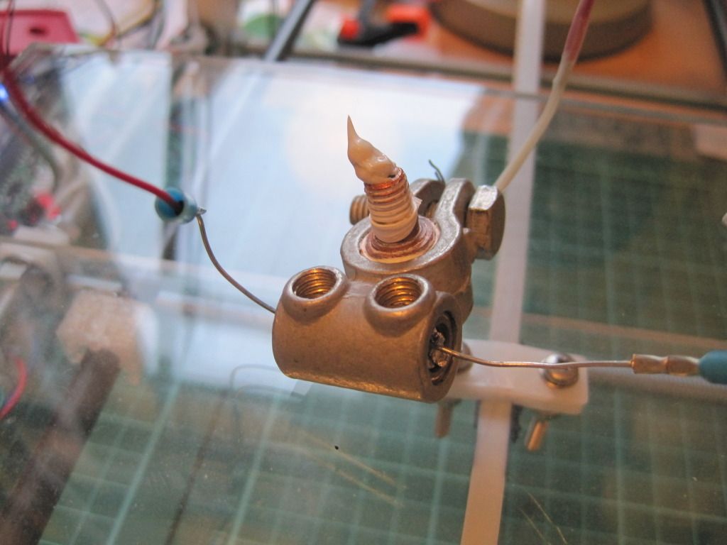
Next I test fitted the heater resistor and its spacing sleeves into the battery clamp. As the following photo shows, there was still a gap to eliminate.
Remembering a tip from the forums, I wrapped the outer sleeve and the resistor with tin-foil, until they were a tight fit within the clamp.
Next I mounted the extruder body to the X-carriage and wired it up. I mounted a terminal block with cable ties through the fan mounting holes on the carriage.
I loaded up the feedstock and performed the E_steps_per_mm calibration for volumetric extrusion as found (prusa method: insert link here).
I performed the calibration with the hotend removed for ease. I ended up with a figure of (EDIT, May 2012: I found my initial E steps figure during a tidy up - I worked it out to be 488.4)
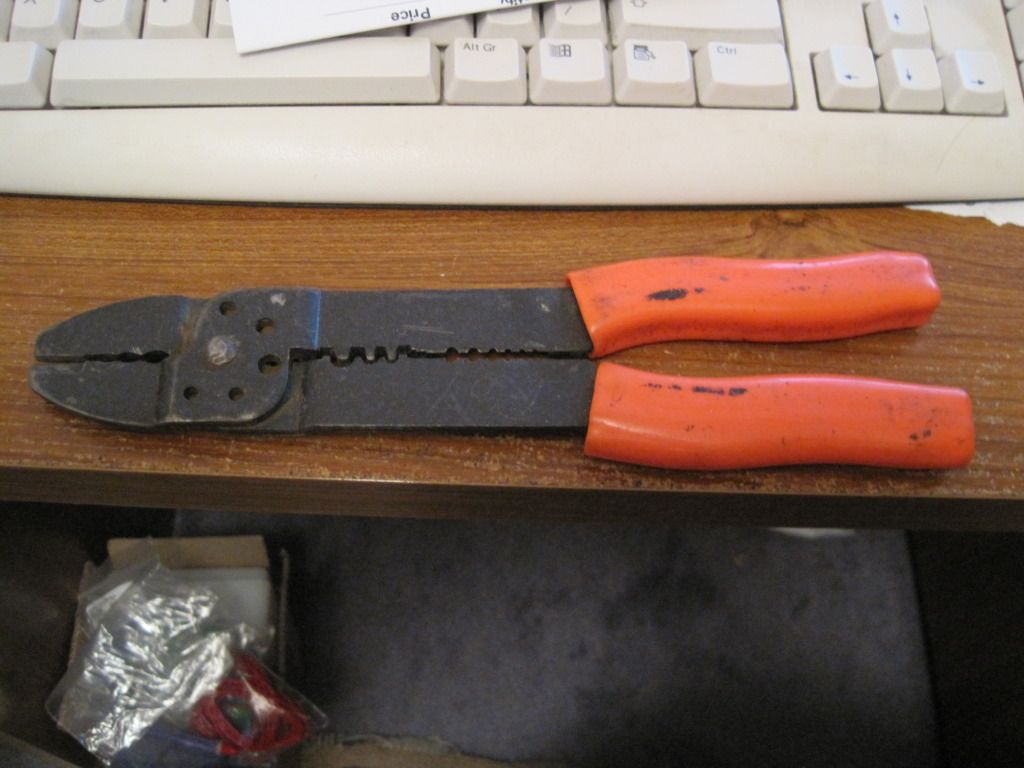
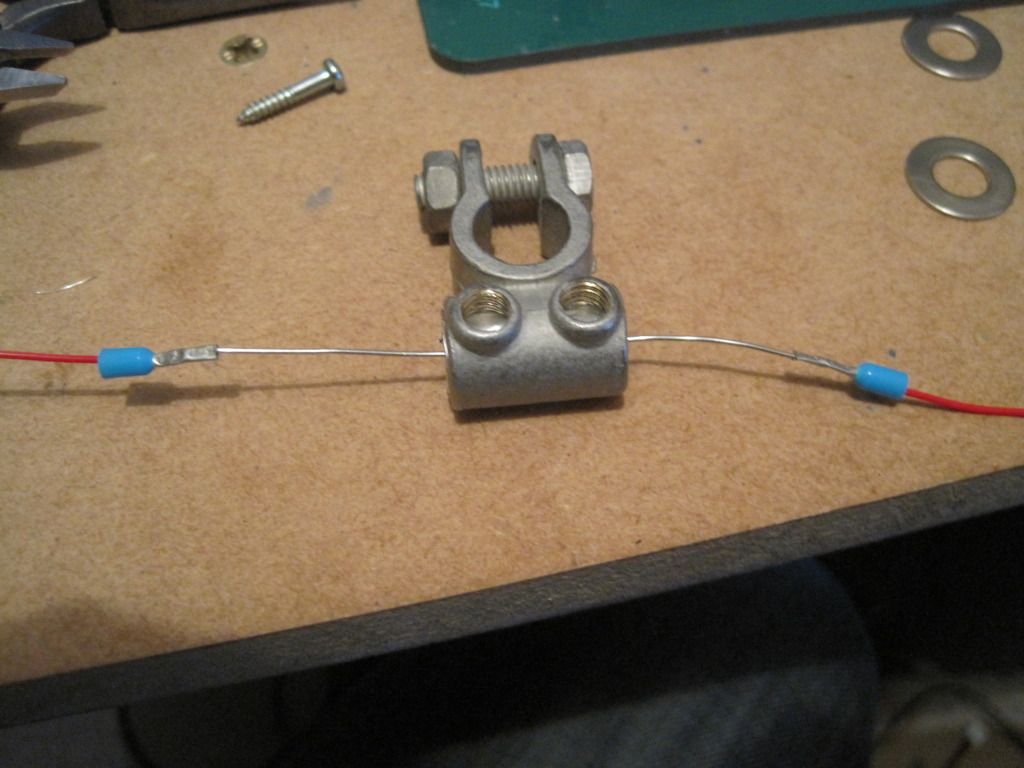
I prevoius look around my Girlfriend's Dad's garage had provided me with a crimping tool, that I used to fit some PTFE wire to the resistor legs via a pair of bootlace ferrules. Isn't it funny that sometimes the right tool turns up at the right time?
I covered the outer nozzle sleeve in a thin layer of heat sink paste, and set about clamping it into place. I had thought this to be a fairly easy task, but it turned out to be much harder than I had anticipated. The outer sleeve wasn't really big enough and so there was a very large reduction to be made by the clamp's bolt. Eventually I had to resort to a pair of pliers, as the bolt was distorting the clamp too much. With the aid of a very patient girlfriend, it was eventually tightened up.
I fitted the sensor as far into the hole as it would fit, and held it in place with a small peice of wire.
I screwed the mig tip into the barrier, and tightened it up. Then I fitted the heater and thermistor wires into the terminal block, and competed the wiring to the board.
Next up: Will it actually work...?
Thursday, 20 October 2011
Chapter 21 - In which I (finally) start the long-awaited hot-end post!
Firstly let me say that progress has been made recently - quite a lot in fact. But that's for a later post. For now, lets catch up on the last couple of weeks/months as I set out to solve the conundrum of the hot end....
For those of you who may have missed my first post, I started out on this project with no idea of what to use for the hot end, or how to make one. The tools in my garage are pretty much limited to a powerdrill and an electric screwdriver! I decided to build a hot end design that I could realistically make in my garage, without the use of a lathe, pillar drill or any other fancy machinery.
The hot end basically consists of several parts: the nozzle, the heater barrel, the thermal barrier, a heater block, a heater, and a temperature sensor.
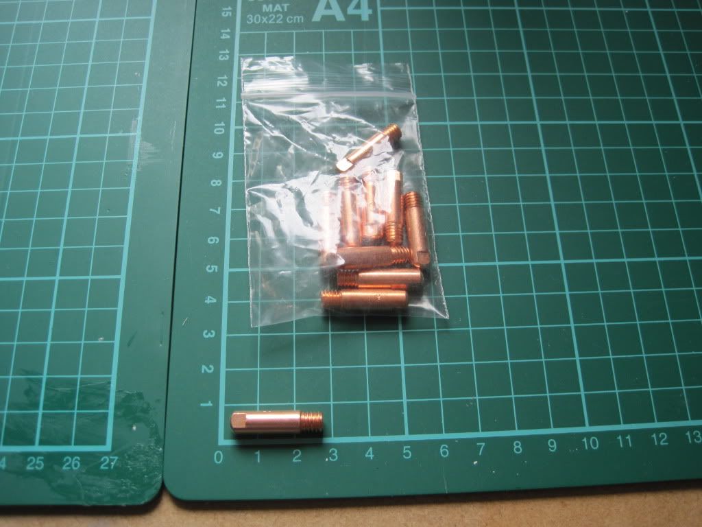
The Prusa CAD model on the wiki includes a basic hot end setup. It uses a 0.6mm MIG welding tip as the nozzle/heater barrel, although the details of the heater are left off. MIG tips are not expensive, and so I picked up a 10-pack from ebay:
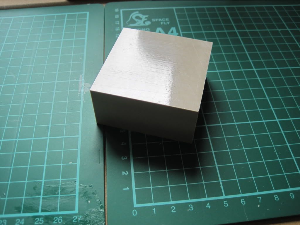
The hole in the bottom of wade's extruder body is 16mm, so I bought some 16mm outer diameter PTFE rod. This will act as the thermal barrier between the hot end and the extruder body.
Some designs use a PEEK thermal break, and I happened across some for a good price on ebay. I've not used it yet.
Now for the heater block. This is the one part that really stumped me. I didn't really fancy trying to get hold of Nichrome wire and wrapping the nozzle in it, so I decided to use a block of some sort. I figured that without a drill press or pillar drill, there was no way I could accurately machine one for myself, so I spent a long long time searching for something suitable and pre-made.
I came across these and these on screwfix. they are for bonding wire to earthing rods, but would perform well here as they are brass and have a clamp built in to hold them onto the nozzle. The drawback is that they would need another hole of some sorts drilled into them for the heating resistor, and another for the sensor.
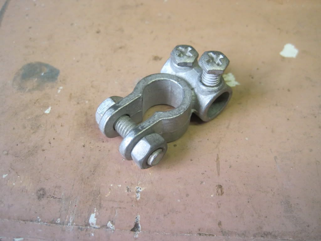
Whilst browsing ebay, I came across car battery terminals. They looked spot on - a larger hole for fitting the nozzle through, and a smaller one at right-angles for the heater. After another long search, I found the smallest ones I could. They are for (older?) Nissans, that use smaller terminals on their batteries, and in particular the negative terminal as it is slightly smaller than the positive. I bought a couple from ECS.
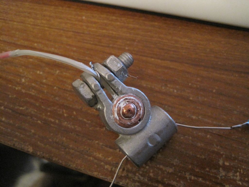
The last problem to solve was how to bulk out the ~6mm diameter MIG nozzle to the ~12 internal diameter of the clamp. Eventually I settled on using a series of copper pipes, cut into sleeves of ascending diameters. I would also use this method to fit the resistor into the 10mm cable hole in the clamp.
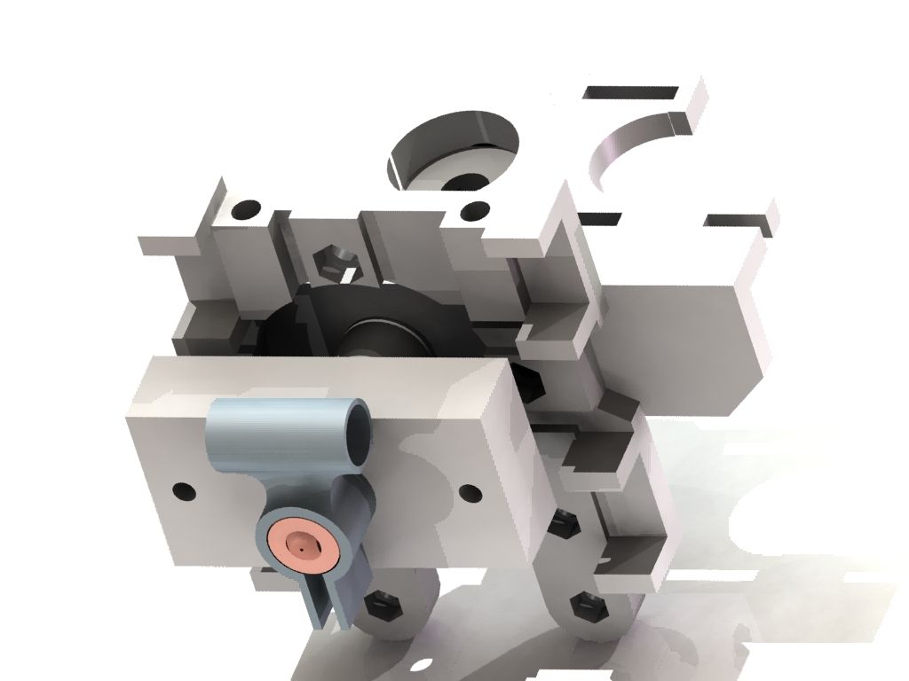
I 3D modeled the whole assembly, and fitted it to the X carriage and wades parts:
The large rectangle above the clamp is the PEEK block, cut down. This would have had the thread cut into it to hold the nozzle, and have been held to the assembly with long bolts that also held the extruder body to the carriage. The more I thought about it, the more I worried that coupling the extrusion force directly to the carriage like this would snap the carriage. Eventually I dropped the PEEK, and decided to just use PTFE, and couple it via the screwholes in the extruder body.
Blogging about it seems to trivialise the process a little. I seem to recall spending ages thinking, doodling and searching, trying to find something that would work right, and the struggling to fit it all together in my head.
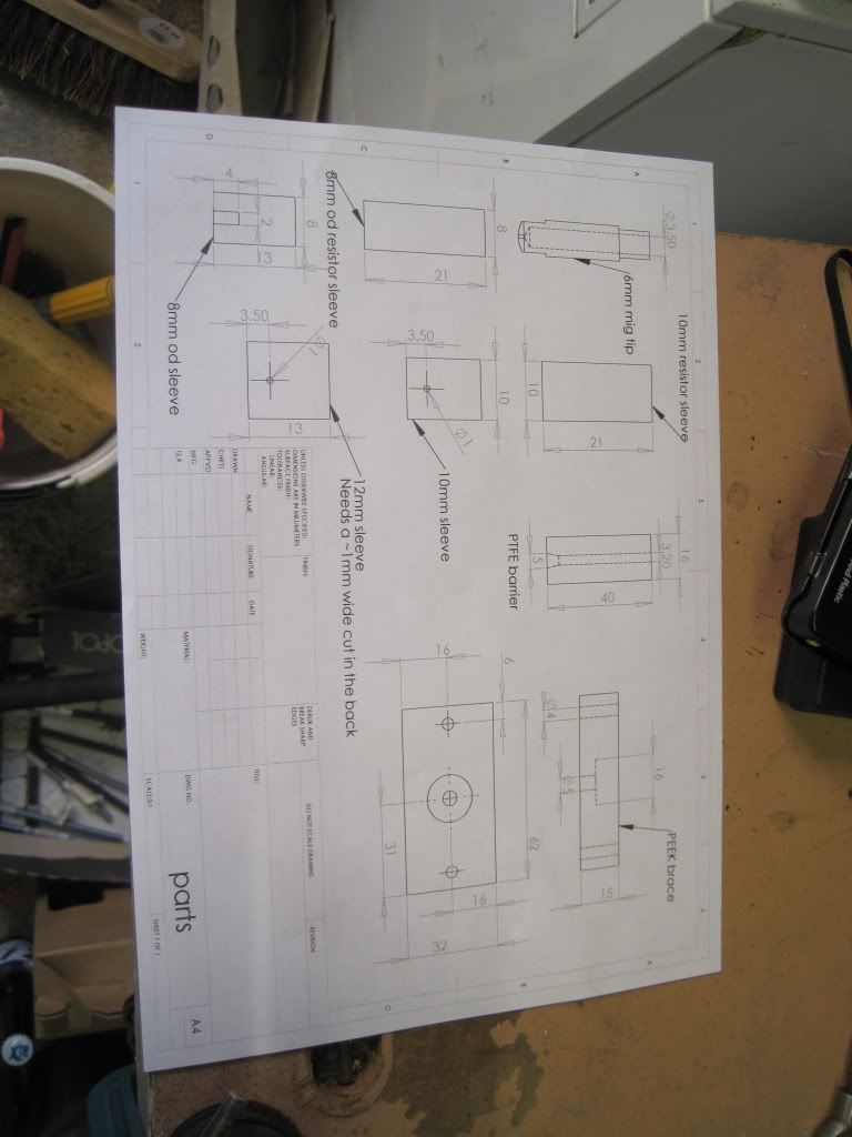
Once I had settled on the design, I started to make bits. I used CAD to make a drawing of all the parts that I had to fabricate. (If anyone wants to replicate this madness, I am happy to post/supply my drawings and models. I might upload to the wiki if this actually works as intended!)
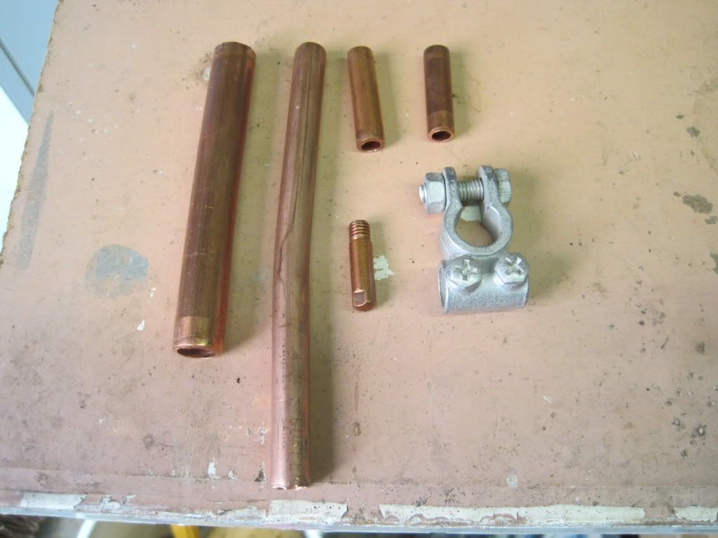
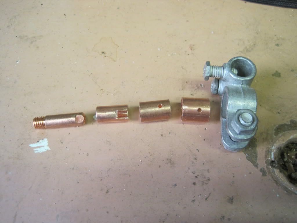
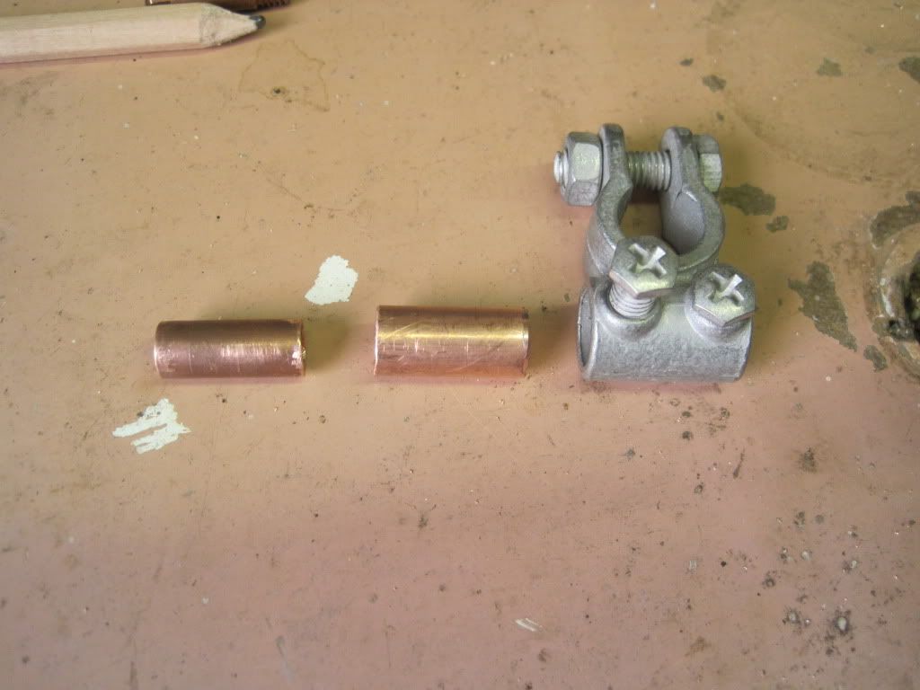
Here are the parts laid out. The copper pipe is some scrap bits that I collected, in 3 sizes.
Fast forward through lots of sawing, and drilling pipe to expand the diameters a bit:
I drilled the MIG tip out to 3mm internal diameter, as deep as I dared. I had intended to drill it progressively, but the hammer action came on on the drill by accident and snapped the 1.5mm bit I was using, so I started again and just went to full width from the start - it was hard work! The sleeves have holes and slots in them, such that the sensor can reach right though the sleeves and be held captive against the flats on the tip. the tip and sleeves 1 are such a tight fit that I had to turn down the outside of the tip with a file. Sleeve 3 is too large in diameter, so I cut a slot in the back and reduced the diameter (in a manner that my sister - a jeweller - would have cringed at). I also cut down the pipe for sleeving the resistor:
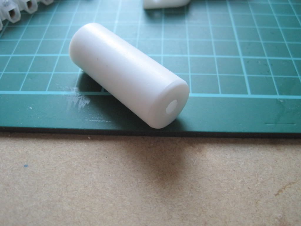
The next job was the PTFE barrier. Shouldn't be too hard, right?
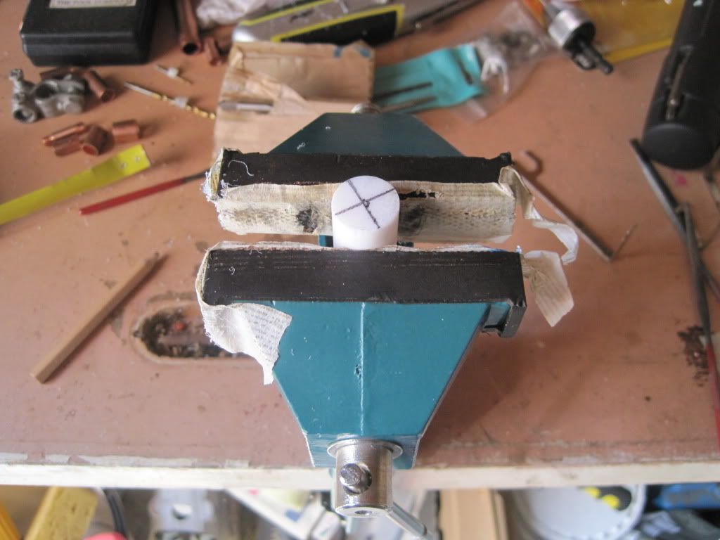
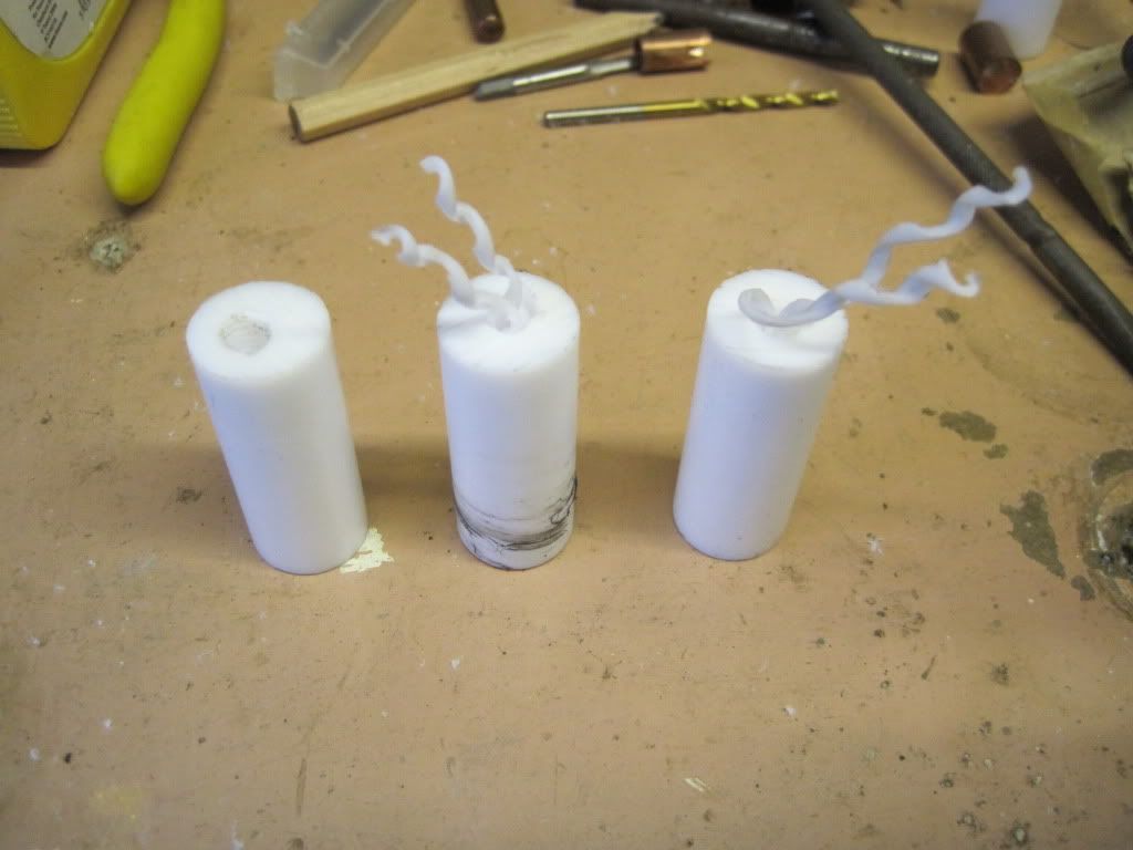
Turns out, it was very difficult. This is the only part that really needed a machine tool. It was very difficult to get the hole straight down the middle. I actually succeeded first time, but then as I tried to drill the counterbore for the thread, the bit "grabbed" too much and went way too deep, ruining the part. The two subsequent tries were as bad, or worse:
I encountered one of the lowest points so far on the project. I just couldn't do this bit, no matter how hard I tried. I had seen somewhere the notion that a reprap should be buildable in the garage, with no special tools. I know that I am pushing that definition a long way by having almost nothing in terms of tooling, but the longer I went on the more determined I had been to make the entire printer without machine tools. I thought that if I could invent a design that didn't use anything more than a drill, maybe I had something to add to the reprap world. It looked like I just couldn't do it.
Eventually I decided that I had come too far to give up. I'm really interested in printing afterall, and taking this hardcore home-fabbing approach wasn't getting me any closer to my goal. Grudgingly I set aside the idea of a machine tool-free hot end, and took the remaining PTFE into work. Less than 10 minutes on the lathe produced a lovely looking thermal barrier:
I took it home and tapped it to M6:
I used heat-sink compound between the layers of sleeves to remove the air gaps. It's not as conductive as metal is, but much much more so than air. I made sure the coating was very thin, just enough to eliminate any air gaps. I tapped the sleeves together with a hammer, using a two blocks of wood to protect the ends.
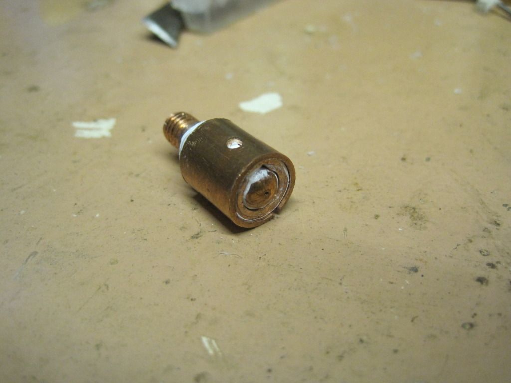
Here is the nozzle completed:
It feels fairly solid, with the exception of the outer sleeve which has to stay loose until it is clamped.
So that's my hot-end. Next up: all the fun of mounting the extruder, hot end and other stuff!
For those of you who may have missed my first post, I started out on this project with no idea of what to use for the hot end, or how to make one. The tools in my garage are pretty much limited to a powerdrill and an electric screwdriver! I decided to build a hot end design that I could realistically make in my garage, without the use of a lathe, pillar drill or any other fancy machinery.
The hot end basically consists of several parts: the nozzle, the heater barrel, the thermal barrier, a heater block, a heater, and a temperature sensor.
The Prusa CAD model on the wiki includes a basic hot end setup. It uses a 0.6mm MIG welding tip as the nozzle/heater barrel, although the details of the heater are left off. MIG tips are not expensive, and so I picked up a 10-pack from ebay:
| They have a 0.6mm hole straight through the length of the body, and are threaded to M6. |
Some designs use a PEEK thermal break, and I happened across some for a good price on ebay. I've not used it yet.
Now for the heater block. This is the one part that really stumped me. I didn't really fancy trying to get hold of Nichrome wire and wrapping the nozzle in it, so I decided to use a block of some sort. I figured that without a drill press or pillar drill, there was no way I could accurately machine one for myself, so I spent a long long time searching for something suitable and pre-made.
I came across these and these on screwfix. they are for bonding wire to earthing rods, but would perform well here as they are brass and have a clamp built in to hold them onto the nozzle. The drawback is that they would need another hole of some sorts drilled into them for the heating resistor, and another for the sensor.
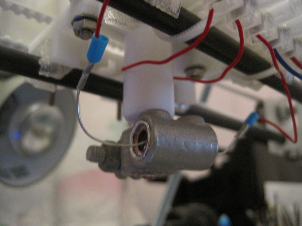
Whilst browsing ebay, I came across car battery terminals. They looked spot on - a larger hole for fitting the nozzle through, and a smaller one at right-angles for the heater. After another long search, I found the smallest ones I could. They are for (older?) Nissans, that use smaller terminals on their batteries, and in particular the negative terminal as it is slightly smaller than the positive. I bought a couple from ECS.
The last problem to solve was how to bulk out the ~6mm diameter MIG nozzle to the ~12 internal diameter of the clamp. Eventually I settled on using a series of copper pipes, cut into sleeves of ascending diameters. I would also use this method to fit the resistor into the 10mm cable hole in the clamp.
I 3D modeled the whole assembly, and fitted it to the X carriage and wades parts:
The large rectangle above the clamp is the PEEK block, cut down. This would have had the thread cut into it to hold the nozzle, and have been held to the assembly with long bolts that also held the extruder body to the carriage. The more I thought about it, the more I worried that coupling the extrusion force directly to the carriage like this would snap the carriage. Eventually I dropped the PEEK, and decided to just use PTFE, and couple it via the screwholes in the extruder body.
Blogging about it seems to trivialise the process a little. I seem to recall spending ages thinking, doodling and searching, trying to find something that would work right, and the struggling to fit it all together in my head.
Once I had settled on the design, I started to make bits. I used CAD to make a drawing of all the parts that I had to fabricate. (If anyone wants to replicate this madness, I am happy to post/supply my drawings and models. I might upload to the wiki if this actually works as intended!)
Here are the parts laid out. The copper pipe is some scrap bits that I collected, in 3 sizes.
Fast forward through lots of sawing, and drilling pipe to expand the diameters a bit:
I drilled the MIG tip out to 3mm internal diameter, as deep as I dared. I had intended to drill it progressively, but the hammer action came on on the drill by accident and snapped the 1.5mm bit I was using, so I started again and just went to full width from the start - it was hard work! The sleeves have holes and slots in them, such that the sensor can reach right though the sleeves and be held captive against the flats on the tip. the tip and sleeves 1 are such a tight fit that I had to turn down the outside of the tip with a file. Sleeve 3 is too large in diameter, so I cut a slot in the back and reduced the diameter (in a manner that my sister - a jeweller - would have cringed at). I also cut down the pipe for sleeving the resistor:
The next job was the PTFE barrier. Shouldn't be too hard, right?
Turns out, it was very difficult. This is the only part that really needed a machine tool. It was very difficult to get the hole straight down the middle. I actually succeeded first time, but then as I tried to drill the counterbore for the thread, the bit "grabbed" too much and went way too deep, ruining the part. The two subsequent tries were as bad, or worse:
I encountered one of the lowest points so far on the project. I just couldn't do this bit, no matter how hard I tried. I had seen somewhere the notion that a reprap should be buildable in the garage, with no special tools. I know that I am pushing that definition a long way by having almost nothing in terms of tooling, but the longer I went on the more determined I had been to make the entire printer without machine tools. I thought that if I could invent a design that didn't use anything more than a drill, maybe I had something to add to the reprap world. It looked like I just couldn't do it.
Eventually I decided that I had come too far to give up. I'm really interested in printing afterall, and taking this hardcore home-fabbing approach wasn't getting me any closer to my goal. Grudgingly I set aside the idea of a machine tool-free hot end, and took the remaining PTFE into work. Less than 10 minutes on the lathe produced a lovely looking thermal barrier:
I took it home and tapped it to M6:
I used heat-sink compound between the layers of sleeves to remove the air gaps. It's not as conductive as metal is, but much much more so than air. I made sure the coating was very thin, just enough to eliminate any air gaps. I tapped the sleeves together with a hammer, using a two blocks of wood to protect the ends.
Here is the nozzle completed:
It feels fairly solid, with the exception of the outer sleeve which has to stay loose until it is clamped.
So that's my hot-end. Next up: all the fun of mounting the extruder, hot end and other stuff!
Subscribe to:
Posts (Atom)