Here are the majority of the parts I purchased:
 |
| Mechanical parts |
 |
| Electronics |
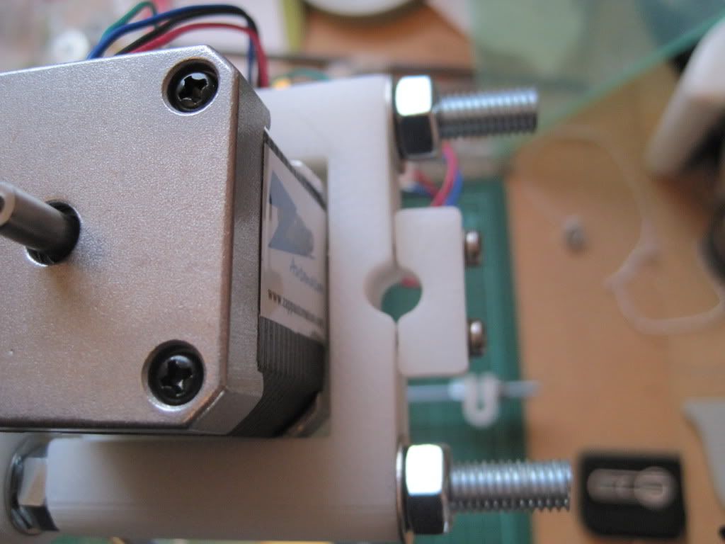
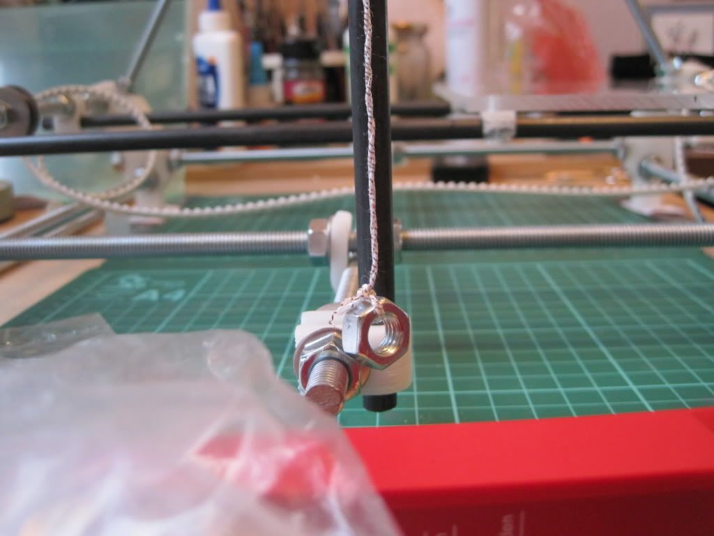
I got back to work by attaching the Y axis stepper motor. We don't carry M3 by 10mm screws at work, so I got 12mm long ones instead. I knew that the motor screw holes bottom out and that 12mm would be too long, so I got some spring washers to take up the slack.
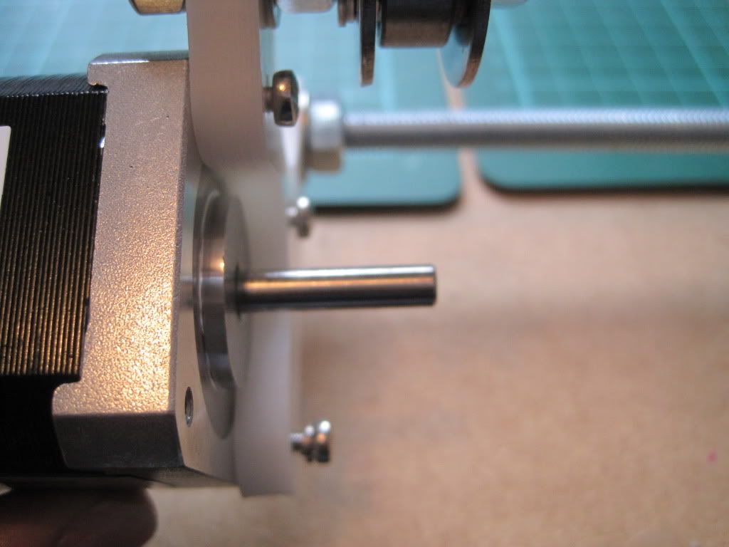 |
| The screws fully seated - you can see the slack caused by them being too long. The bottom screw has the spring washer fitted. |
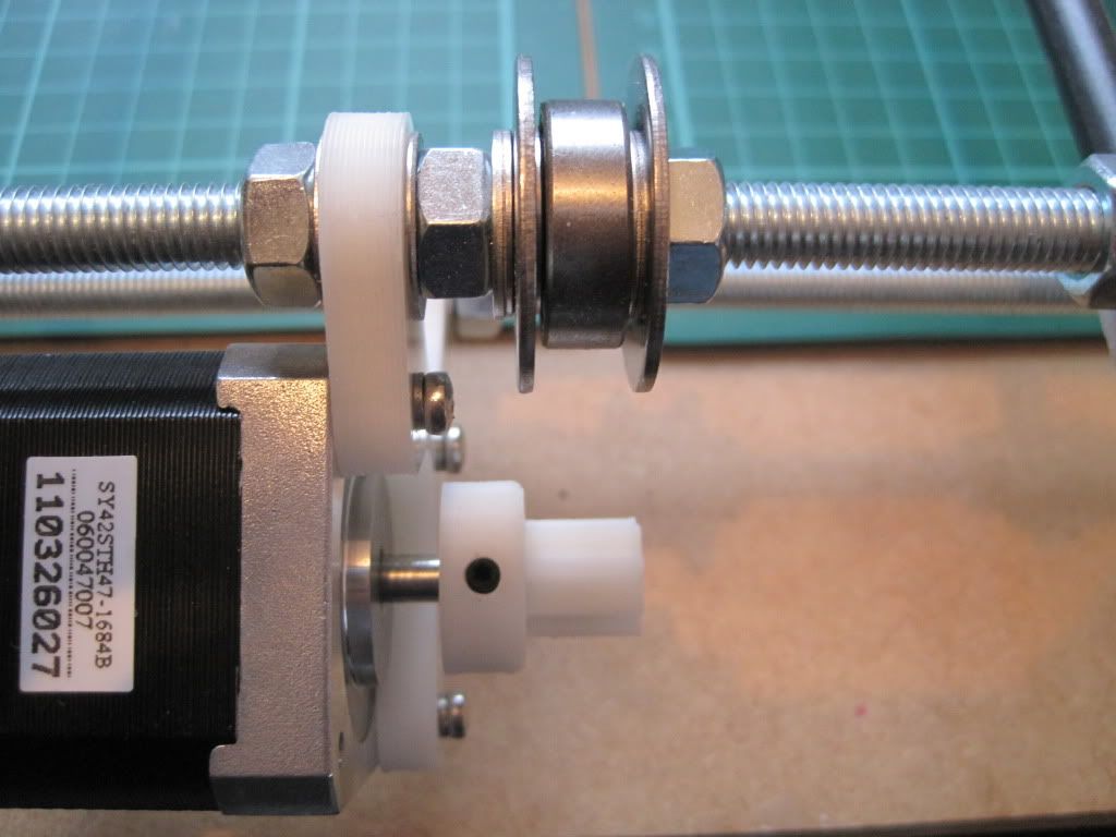
Next I fitted the pulley to the motor shaft. I had gotten a couple of pointy grub screws, thinking that flat ended ones wouldn't grip the shaft well, but hadn't looked at the screws Nophead had supplied. These turned out to be pointed as well, so I kept them (thanks Nophead!). I aligned the pulley with the bearing and tightened it into the shaft before checking that it gripped well and didn't turn. At the same tie, I moved the Y axis bearings closer to the middle of the frame. They were a way off to one side, and I was worried about off-centre forces affecting the movement of the axis. I brought them as close to the centre as possible.
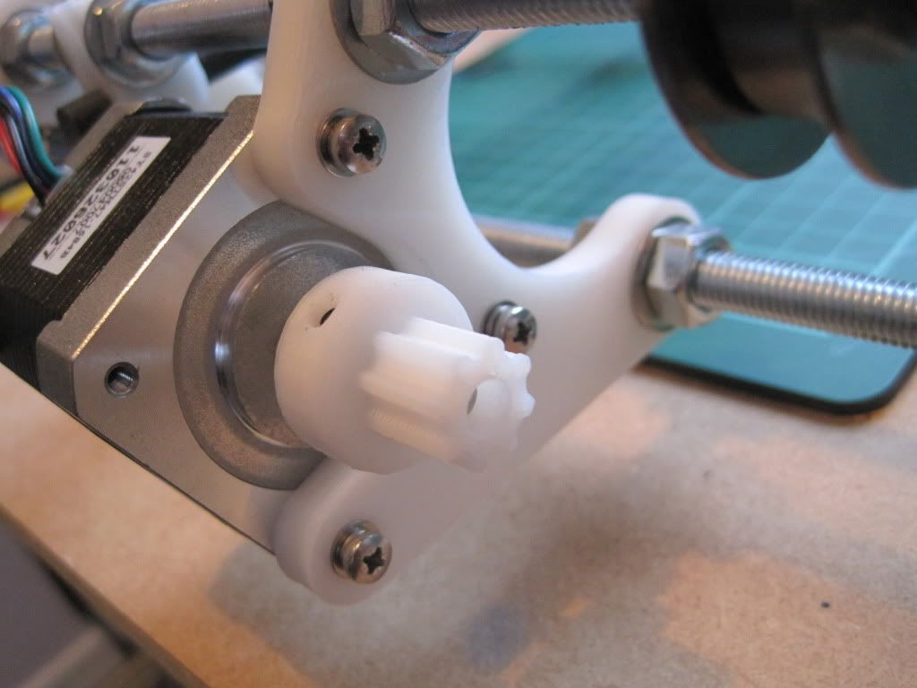 |
| I realised I had forgotten the plain washers behind the spring washers. I went back and fitted them. |
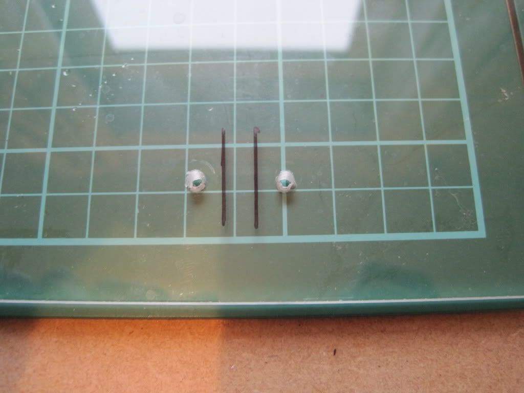
I wrapped the Y axis belt (the shorter of the 2 supplied) around the bearings and lined it up over the lower sheet. I marked where it lay on the sheet, and started to carefully remove the sheet form the Y axis smooth rods. Then, disaster! - the bushings came off. Whilst the superglue had done a good job of holding it while it was flat, it cracked when I started to move it vertically.

I took the sheet off completely and used the opportunity to mark up the clamp holes and drill them.
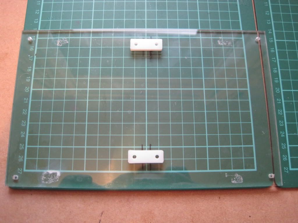
I glued the lower tray down to the bushings again, and will continue with the fitting and tensioning of the belt when the glue is dry. The only good thing to come of this is that the movement seems a little smoother now I've reglued it. Perhaps the bushings were misaligned when I fitted them initially.
Whilst waiting for the glue to dry, I figured I'd make a start on the X axis. Here are the ends:
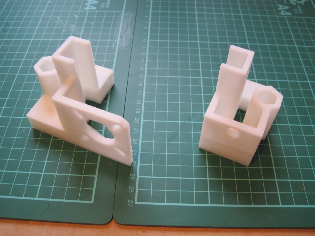
The holes are all the right size, so no need to drill anything out. I fitted the nuts into the traps, which was a little fiddly. I used the end of a file to make them lie flat when needed:

I fitted M3x12 screws into the nuts (again lacking in 10s). These seem excessive (although they may have something important to do later), and I think that M3x8 or even 6 would be better.

The visual instructions say to lay the parts out 500mm apart, but for the suggested X axis smooth rod length of 420mm this was too far:

Anyhow, I fitted the X ends to the rods, and tightened the screws:
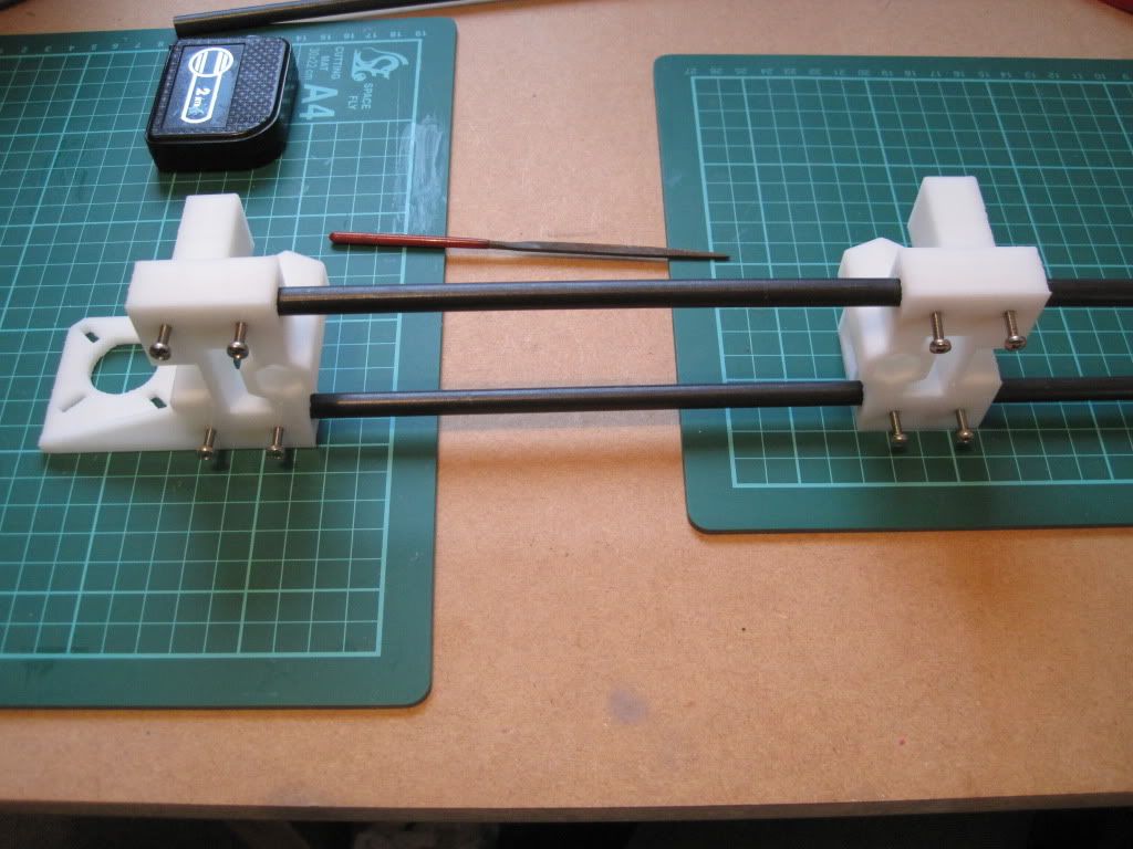
I built the X end idler bearing onto a 50mm piece of threaded rod, and fitted it, and that's the X axis done for now:
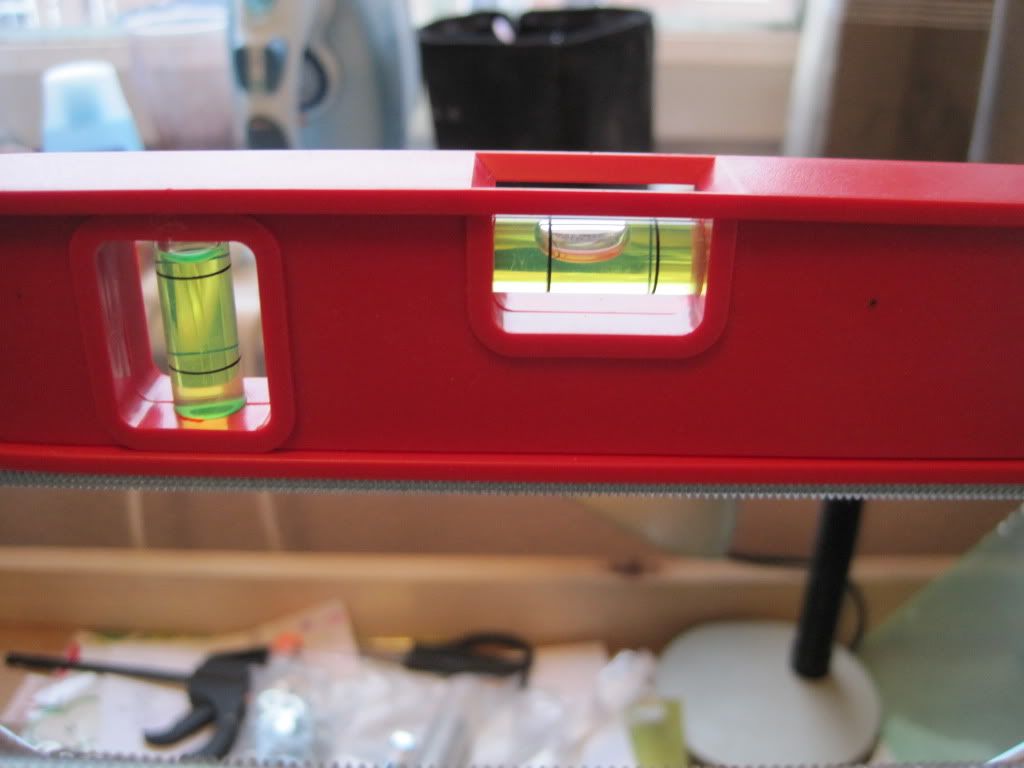
The next job is to level the printer. Mine was a bit wonky:
A pair of plastic rules provided the bulk of the adjustment required, with folded post-it notes providing the fine-tuning.

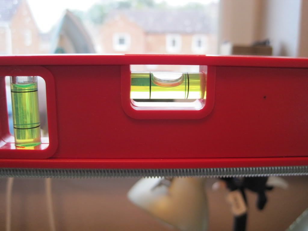 |
| After adjustment - nice and level. |
I have a snap-on adjustable foot in mind as one of my first upgrades....
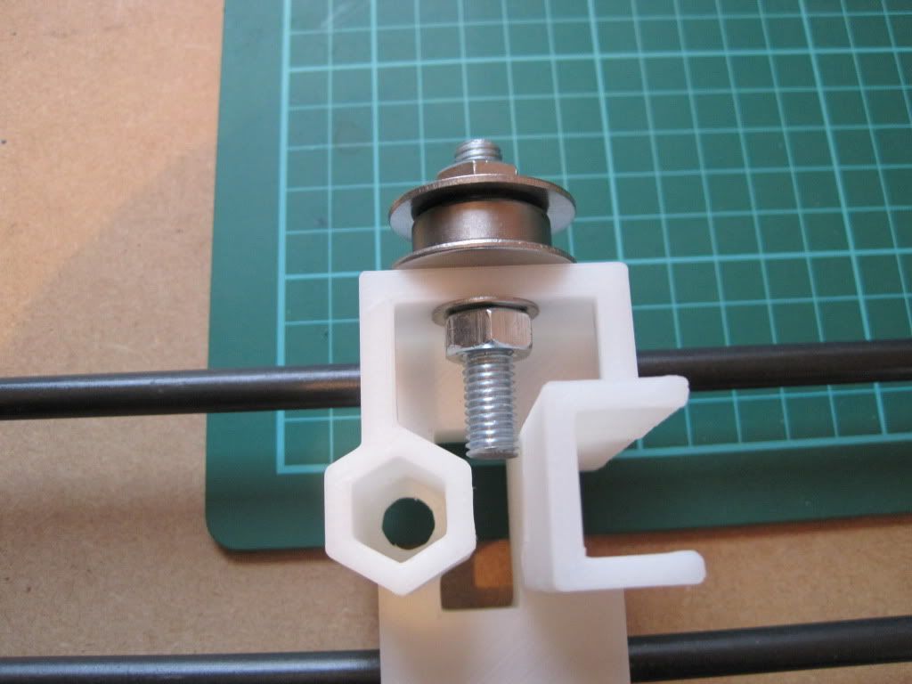
The preliminary adjustment of the Z rod fixings went well, and I moved on to the upper fixings. I fitted up M3x25 screws as suggested in the assembly instructions, but found they were too long. I hadn't read far enough ahead to spot the note about this! I was on the brink of turning the screws around and trying them in reverse, when I looked back at my parts list. I realised I had gotten the correct amount of 20mm screws, so I replaced the 25s and the rod restraints now fit well:
 |
| I test fitted a motor to make sure the screw threads didn't protrude too far - they don't. |
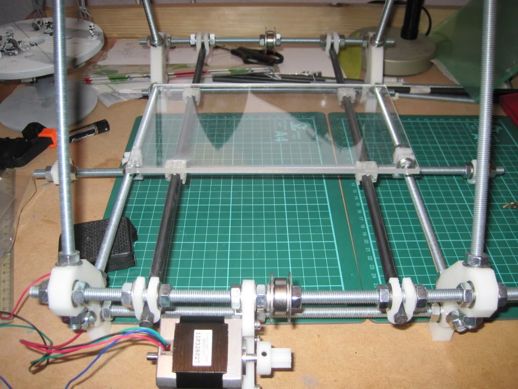
So here is the machine after all of today's exertions. I'll let the glue dry overnight, and hopefully tomorrow will see the mounting of the X axis.
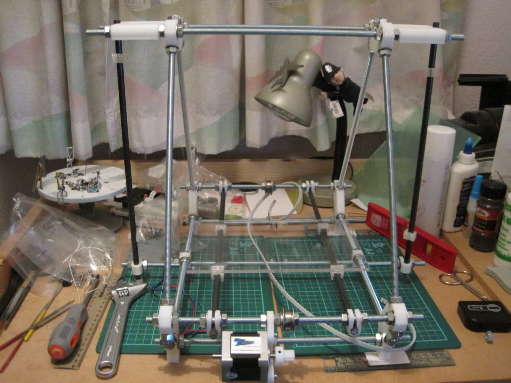
Next up: X's, Z's and leadscrews!
Hi Laurence,
ReplyDeleteThese things take time dont they ? I've attached all my motors and "dry built" my extruder (no hot end yet). I've also stalled with the electronics waiting for my brother to recheck the voltage from my psu before I plug it in (smoke would be bad I think).
Good to see you've got the z-rods straight. I did it by eye to start with which was a stupid mistake. I've also noticed all the bolts on the frame loosen quite easily which may be due to me carrying the printer around. Bit of a pain having to remeasure and retighten all the time.
Theres an interesting method of making a hobbed bolt here :
http://www.thingiverse.com/thing:9291
You've gone for the more hard core self build than I dared. Good luck with the electronics build. Looking forward to your thoughts on the hot end (and hopefully on how it works.....).
Buks
Hi Buks,
ReplyDeleteI've not built the extruder yet, mainly due to not having any springs, however I have had a good idea that ought to solve the problem - it'll be in my next post.
Which version of the electronics did you get? I have got the bits to build mine with the voltage regulator, so I should be able to use a variety of power sources. I was planning on using an xbox PSU, but apparently they have some difficulty with powering heated beds. I may have to rethink that.
My frame has mostly stayed tight, but I haven't handled it much besides the odd case of taking it off the table. You could try adding spring or shakeproof washers next to the nuts, that ought to keep it all a bit tighter.
Your link seems like a good way to hobb the bolt and it results in evenly spaced teeth, however I am without a drill press. I've got a plan in mind though, but it remains to be seen how well it will work. I predict fun times ahead!
Laurence