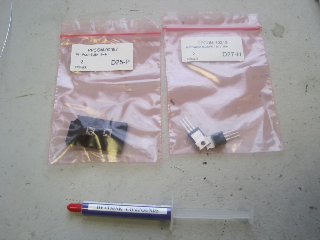
I had to visit several sources to get everything I needed to build the complete board. I bought the MOSFETs that control the heaters and the reset switches (and some heat-sink compound) from protoPIC - http://proto-pic.co.uk/ .
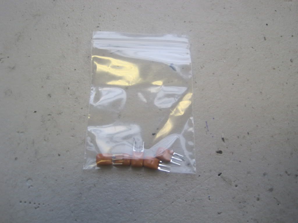
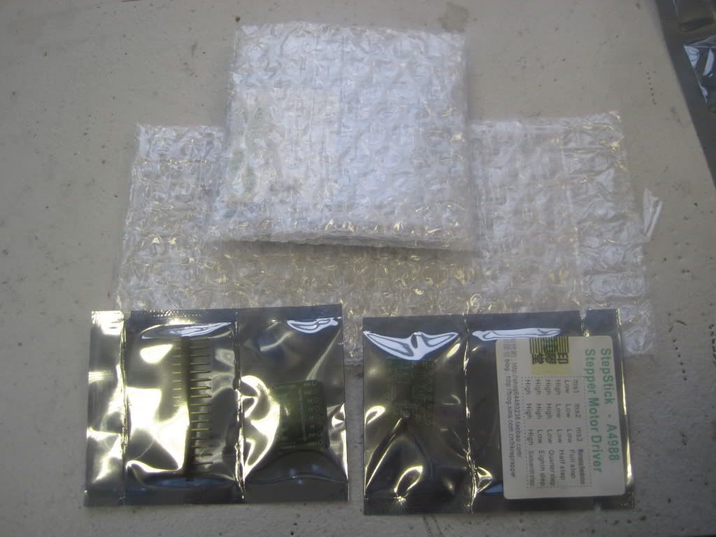
The resonator, pin headers and stepsticks are from ebay:

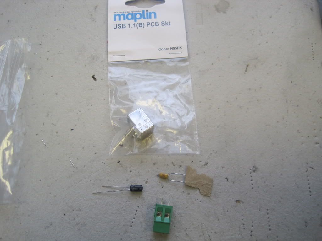
I picked up the USB socket, screw terminal, 0.33uF cap and the 4.7uF cap from Maplins:
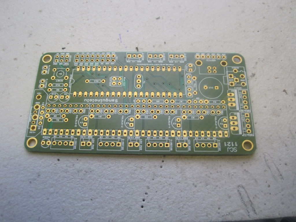
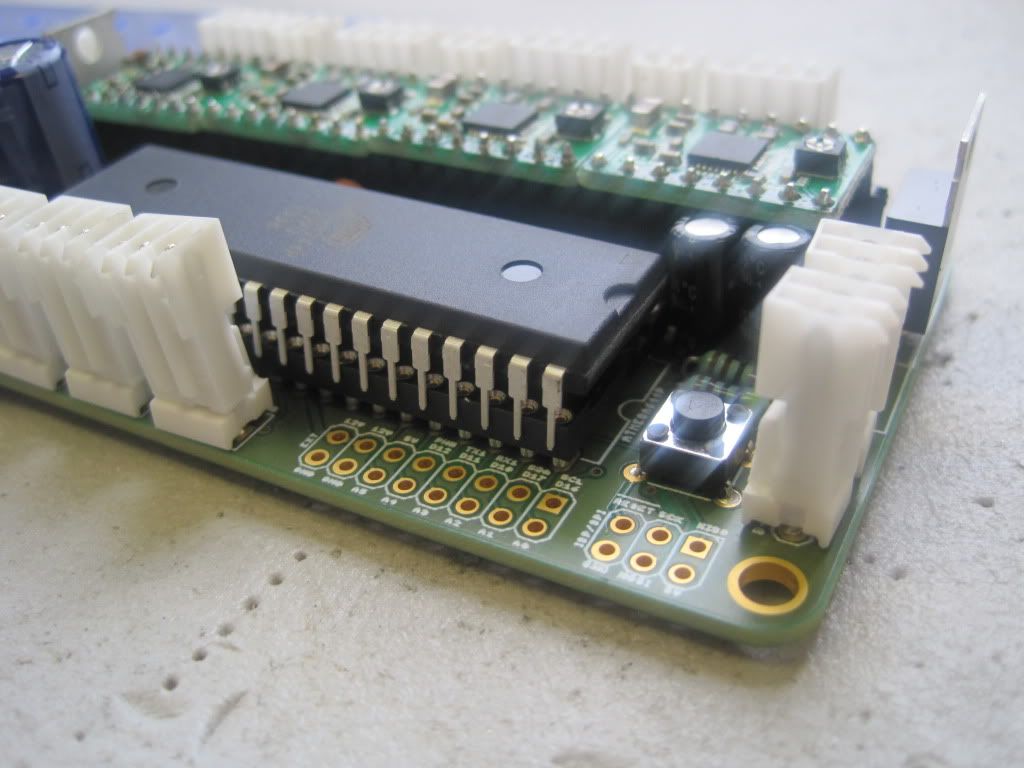
This is the top of the Sanguiniololu 1.1 board:
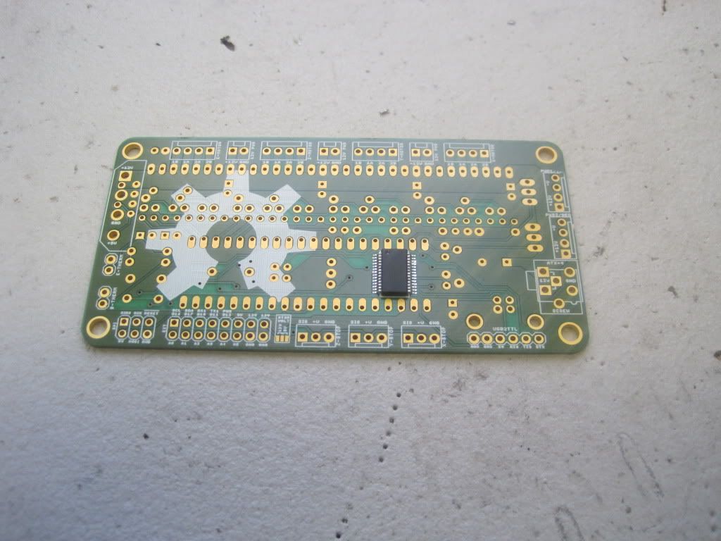
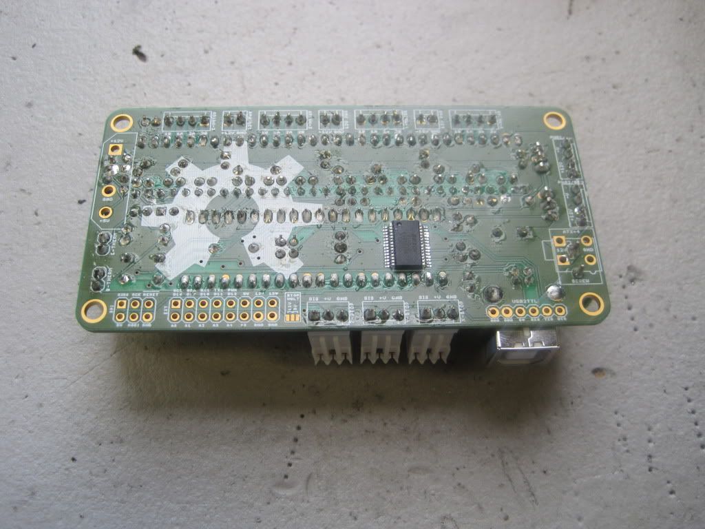
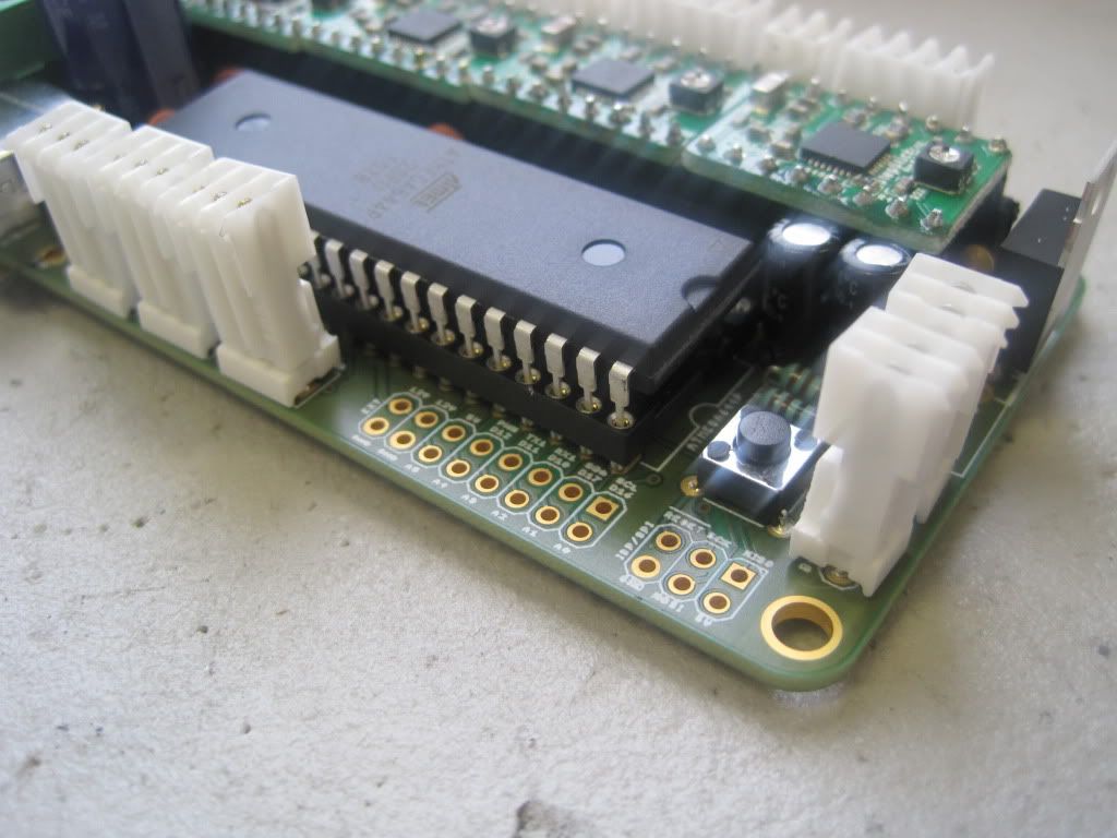
And the bottom - this one has the USB to serial chip already fitted:
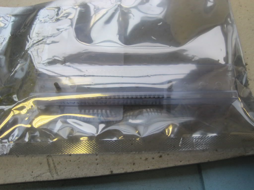
The processor is an ATmega644P-20PU from farnell:
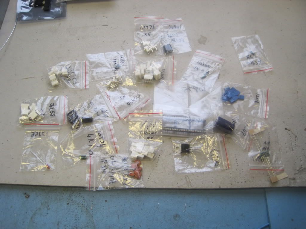
The remaining components are off-the-shelf from work:
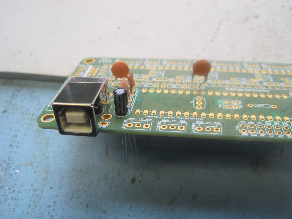
I started the build by fitting the USB components. The 0.1uF capacitors I had chosen were a little bit big, a problem that would recur throughout the build. I used a pair of tweezers to put a bend in the leg to make them fit.
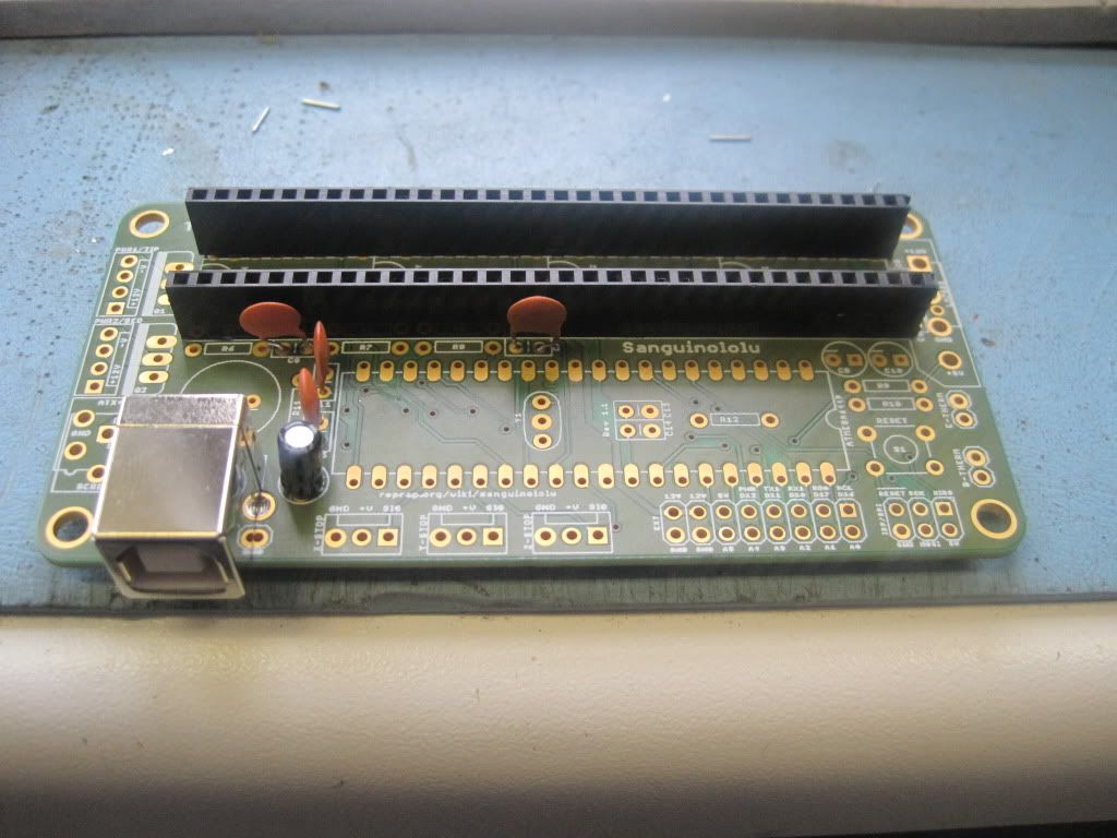
The pin headers I bought were 40 pins long. The build documentation says to use 16 way headers, but the spacing remains constant along the board. I cut the headers down and fitted them.
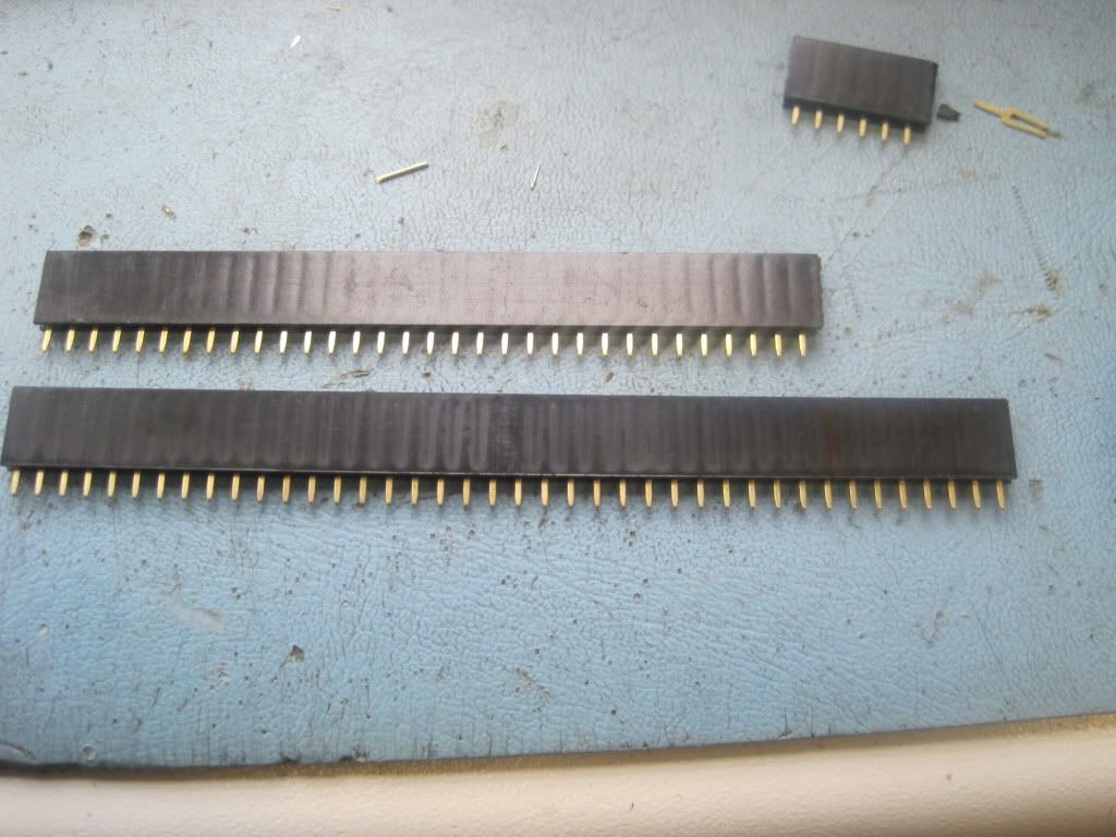
The male pin header was 40 ways as well, but the spacing was different for these. I fitted the jumpers and cut it down:
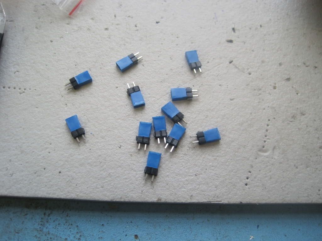
I fitted the jumpers, but they are a pain to keep in place as you turn the board over. They are a bit wonky, but functionally they'll be fine.
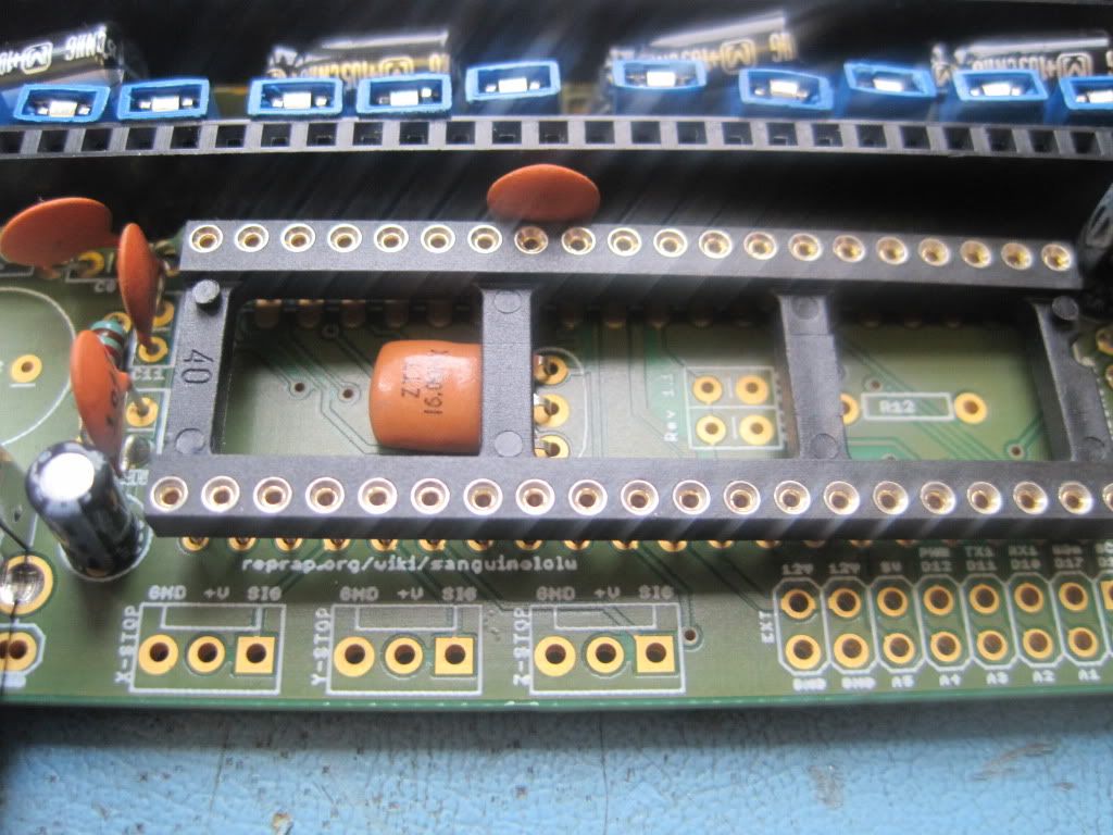
I also fitted the radial caps and resistors between the pin headers:

I put the resonator in place, but then ran into a problem. My socket has 2 horizontal connectors, rather than the 1 as shown in the build photos. It wouldn't fit correctly, so I took a pair of cutters to it and removed the offending brace.
Remember I said those 0.1uF caps were too big? They presented a bigger problem here. They are supposed to be tiny caps that should just bridge the pins and sit neatly in the socket, but these are just too massive. It took a couple of attempts, but eventually I found a way to make them fit into the socket's footprint:
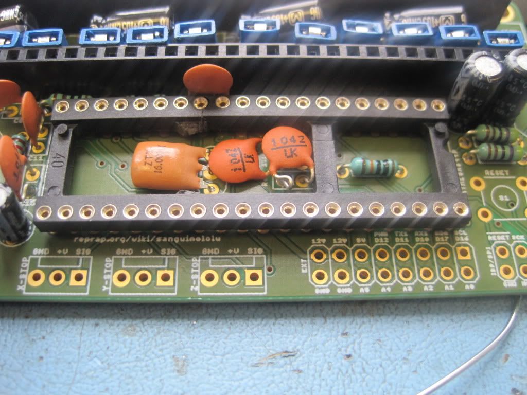
I fitted most of the remaining capacitors and resistors: (please excuse the solder wire and dodgy photography. Some combination of the lighting and low battery level made some of these shots come out a bit blurry)
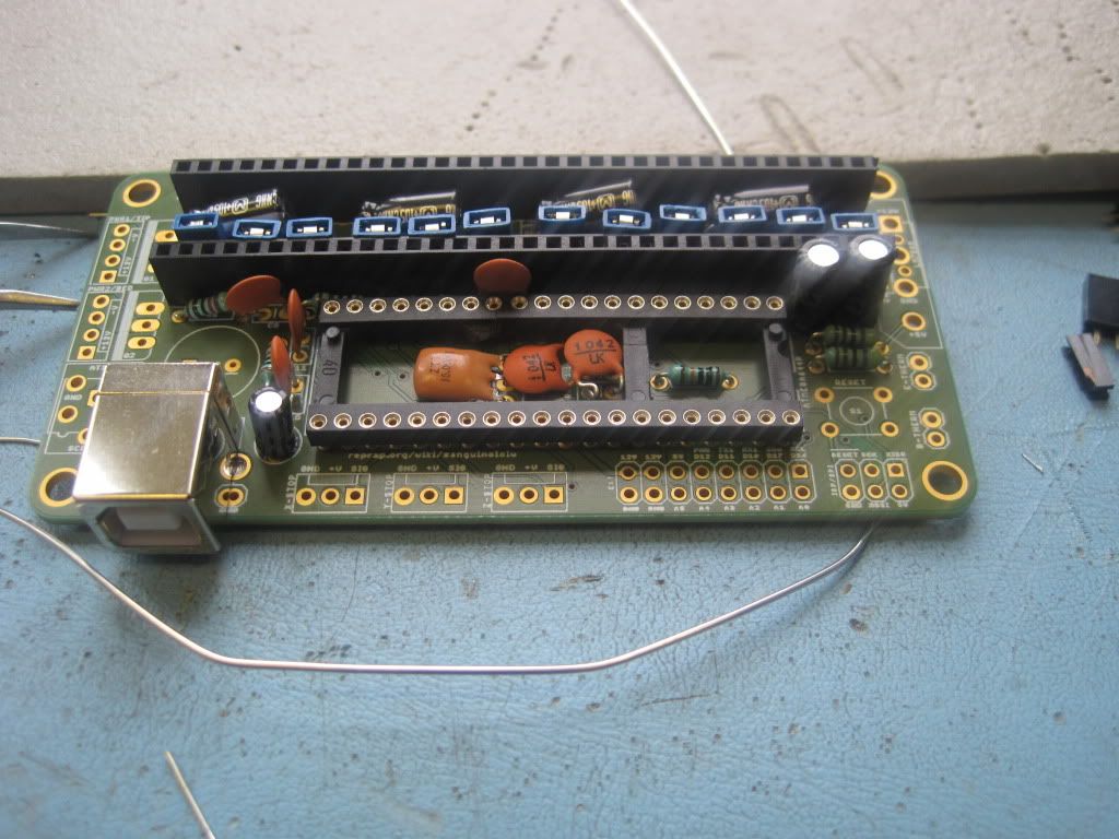
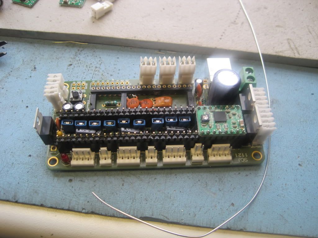
Next I fitted the large charge capacitor, the MOSFETS, reset buttons and LED:
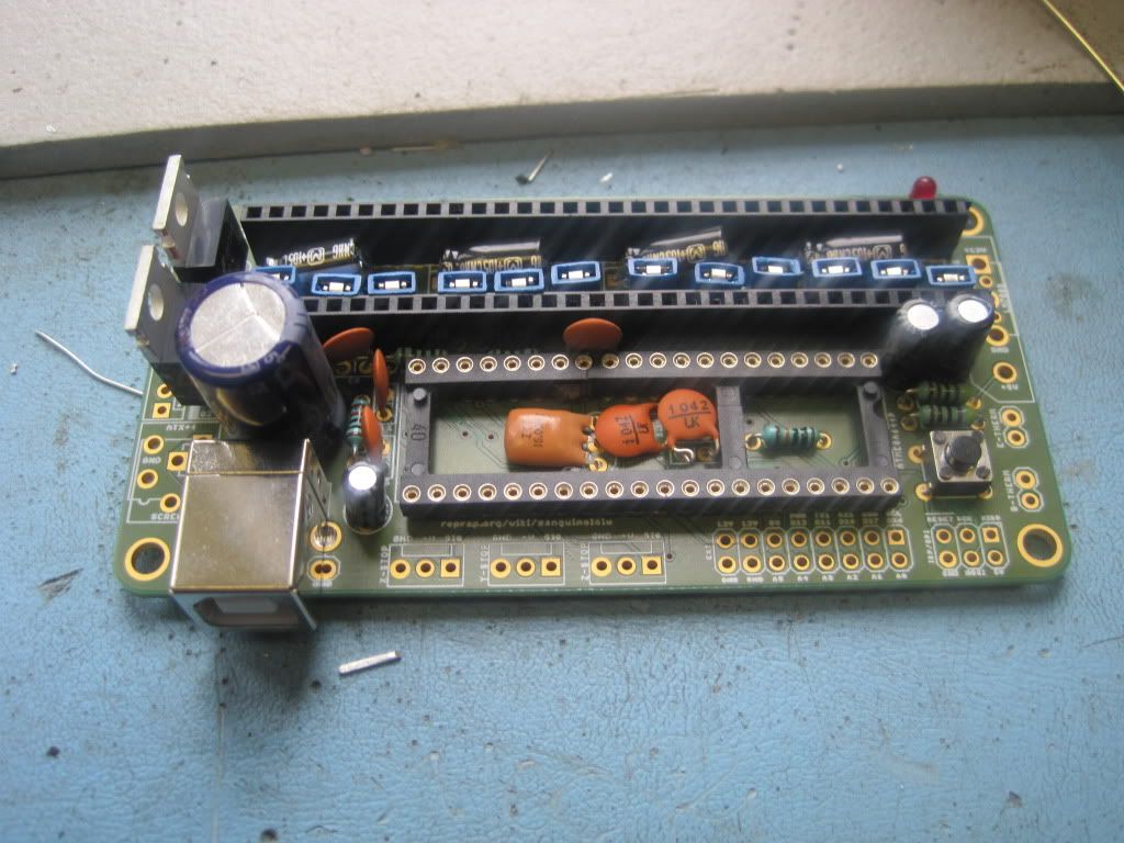
I fitted the edge connectors, 5v regulators and remaining components next, and encountered a slight problem - the 0.33uF cap from maplin was an electrolytic (polarised) one, and I hadn't noticed! I studied the layers in the board, and fitted it with the "+" leg on the +12v side - hopefully this is correct!
I then pushed the stepstick pin headers home, and dropped the board over them.
The stepstick boards needed a little work along the ends to make them sit flush, but they eventually all went down:
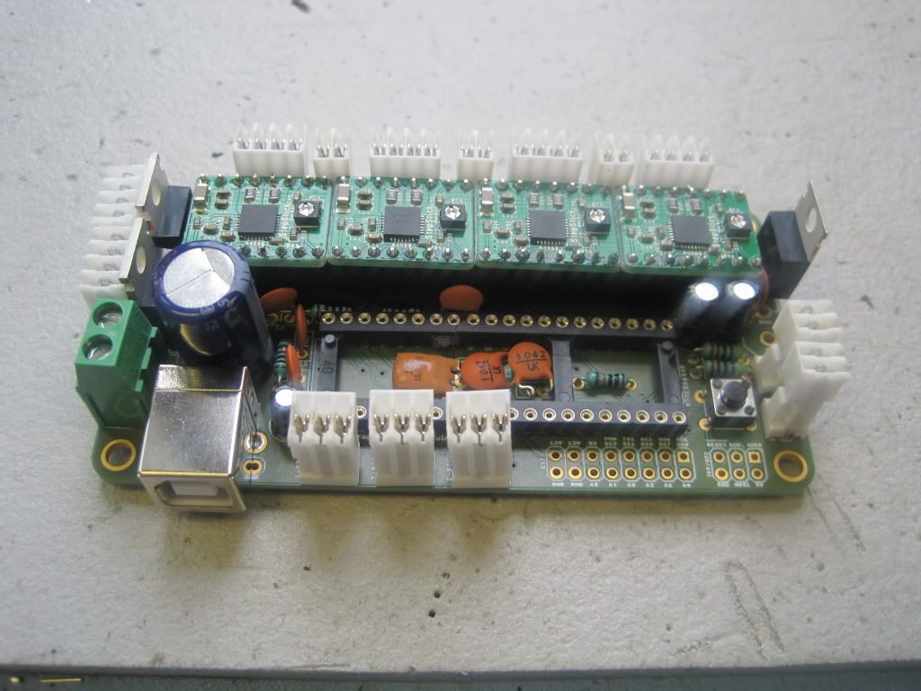
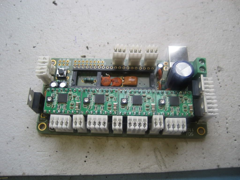
All done, bar the processor. Dry fitted, the legs are too wide for the socket:
This is rectified by running the chip through a "lead setting tool" (is this the same as the "pillow block" mentioned here?):
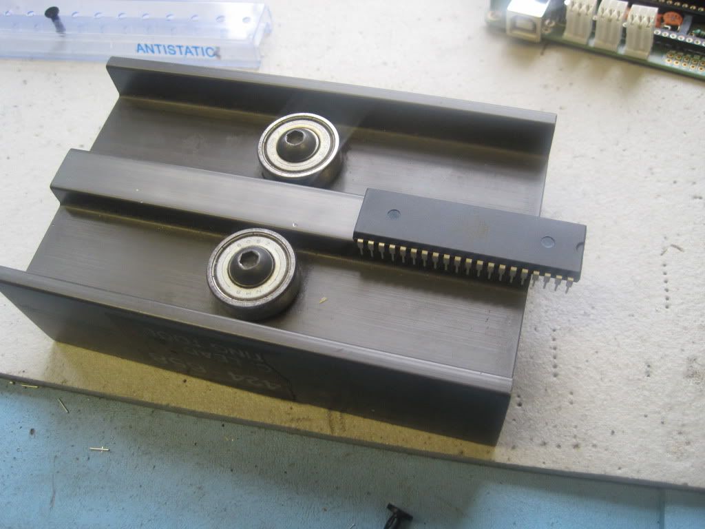
All better:
I didn't push the processor home yet, as I wanted to take the installation etc slowly, and only fit it when I start programming. The full build took just short of two and a half hours.
With the board finished, it was time to plug it in. I found a suitable USB lead, and plugged it into Bernard. After a little thought, I was greeted with the following popup:
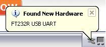
Windows promptly found and installed the drivers, and then did the same for the "USB serial port" - happy days!
And there I left things - not too bad for a friday afternoon. Next up, some extruder mechanics!
No comments:
Post a Comment