Friday 30 September 2011

Chapter 19 - In which there is life!

I've been spending a lot of time recently working on the hot-end, but I'm saving the writeup until I have it completed and can make a whole post.

In the meantime, I've made small amounts of progress in other areas.

I have completed the wiring of the stepper motors for the axes. I wired them all the same, and consequently had to invert the direction in the firmware. I have also resisted cutting down the motor cables for any of the motors. I feel like I might need them longer later, in case I want to swap a motor or something. I realise this is unlikely. I'll cut them down later, if I can get the courage to. In the meantime, the excess cable is neatly bundled with the motors, or on the frame.

Once I had all the motors wired up, I fired up ReplicatorG to move the axes and check the direction was correct. I encountered a strange bug, wherein the axes wouldn't move properly under manual control, sometimes only moving a short distance, and other times moving in reverse. Also sometime multiple axes moved at once! I don't know if this will effect the operation of the machine when printing, but I didn't like it.

I went off and installed Pronterface instead. After the fun I had with sprinter, I was expecting to have some trouble with Pronterface, but was pleasantly surprised. The install guide is concise, but it works perfectly. Printerface needs almost no configuration, and is very quick - I like it! Comes with built in skienforge support too, which is nice. Infact I then went off and got Sfact too, as the pair seem to go together well (pronterface has some sfact-exclusive options).

More recently I have added the endstops to the axes. I'm using microswitches, and they had arms on them:


I popped them into the vice, and sawed off the arms - careful to avoid sawing off the switch!


I decided on locations for the endstops. They are configured as being at the minimum end of the axis in firmware, and so this translates to Y being at the front, the X being at the left, and the Z at the bottom. I played around with locations for a while before marking up the brackets.


I attached the endstops to the brackets with hot glue, as the screwholes were in the wrong places. Each bracket was then fitted to the axis with an M3x25 screw, with a couple of plain washers and a spring washer.  I added some insulating tape to the Y axis terminal, so that it didn't short to the frame.


Once the endstops were installed, I wired them to the plugs and routed the cables along the frame.

I powered on the machine, and tested the endstops. I moved the axis out a long way, and then told it to return. As it was moving I activated the switch. All 3 axes worked ok, stopping the moment the switch was pressed. I then told Pronterface to "Home" the axes. It was pretty scary to watch, as the axes drove themselves into the stops:


In other news, I ordered some filament from Faberdashery. When I tried to load it into the extruder, disaster struck! The hobbed section of my bolt is too narrow, and the filament is too rigid to come into contact with it, regardless of how much pressure is applied by the idler.

I have to hobb a new bolt. I have ordered some M8 by 60 shoulder bolts from ebay, and will hobb the shoulder with an M6 tap - if I can work out a way to do it.

Next up: not sure. Maybe the hot end.

Tuesday 27 September 2011

Chapter 18 - In which my alternate spring source is validated

One quiet Sunday, I sat down to build my extruder. I had already hobbed the bolt, and so now only needed to build up the extruder body.

I had a little trouble fitting the bearings into the extruder body, but a little work with a file ensured that they sat flush:


I had a peice of threaded rod left over from cutting the frame bars down, so I cut it to 50mm and used it to mount the idler bearing. The bearing seems a little loose though, so I may have to change it out in the future.


I fitted M4 by 50mm bolts through the extruder body, and fitted a pair of washers to each one. I had to file out the screw holes a little to make the bolts fit.


I fitted the idler block over the bolts - this was harder that I had thought it would be, due to having to keep the block square or the bolts would bind up.

Now, time for the all important springs. As I mentioned here, I had found a source of springs in a certain shape of clothes peg. I had ordered some after scouring ebay for the right type. Unfortunately when they arrived they were the traditional, sideways-action spring type. I got in touch with the company, whoi were able to find some of the kind their listing showed. Lesson learned by me - some photos on ebay are for illustrative purposes only. Once I had the new, correct, pegs in hand, I set about de-springing them.


Having removed 4 springs, I was faced with another problem - they are too long for the bolts. After failing to compress them enough to get a nut onto the thread, I took them to the garage and took a hacksaw to them.  I cut them down to just the right length to allow them to be fastened on, with only a little compression.


The motor mount on the extruder is thinner then that of the Y axis, so I though I could use the same trick of doubling-up the washers as I did on the x-end-motor. However, This made the Screw heads stick out too far, and they interfered with the gears. I opted for the solution below, with one set of spring washers between the motor and the extruder, and the other next to the screw heads:


I fitted up the hobbed bot and large gear. I had to use 4 M8 washers to space the bolt correctly, because the hobbing had drifted to one side.


I had used a couple of M8 halfnuts that I found to hold the hobbed bolt in place, but have subsequently moved to one half nut and one full nut as I had problems getting the tension right and the locking tight enough.

Because of the extra washers spacing the big gear, I had to mount the small gear in reverse. This is actually suggested in some of the instructions, and won't cause any trouble due to the grub screw still being securely on the shaft.


Next up: talking to the machine

Thursday 22 September 2011

Chapter 17 - In which I finally burn the bootloader

This bootloader business has really tripped me up. As I mentioned 
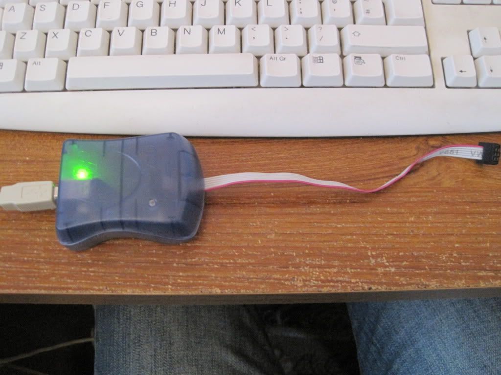
here, I built a parallel port programmer to burn the chip with. Having a quiet Saturday in hand, I set about programming the chip with the bootloader.

Since Bernard doesn't have a parallel port, I loaded Arduino 0018 onto my main machine, along with Sanguinio. I plugged in the prgrammer, connected my sanguiniololu to the USB port (installed the FTDI drivers etc) and ran Ardunio. I set the board type and COM port up, and then selected "Burn bootloader w/ parallal programmer" and sat back and watched it program.

Actually I sat back and watched it fail. I got the following error message:
avrdude: initialization failed, rc=-1
avrdude: Yikes!  Invalid device signature.
avrdude: Expected signature for ATMEGA644P is 1E 96 0A
avrdude: AVR device not responding
 ***failed;
avrdude: verification error, first mismatch at byte 0x0000
         0x3f != 0x00
avrdude: verification error; content mismatch

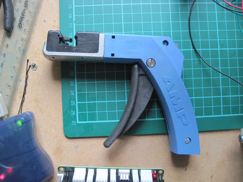
I tried a couple more times, and still got the same message. I decided to give up on the parallel programmer, and use an AVRISPMKII programmer that I had borrowed in case this happened:


I plugged it in and watched the computer try and locate some drivers fir it, but it failed. I went off to Atmel's website to download the software I needed - AVRstudio 5. 600megs and some time later I tried to install it, and was once again met with failure: AVRstudio needs win XP Service Pack 3, which is not installed on my machine.

I transferred the setup to Bernard and installed it there, along with its prerequsities, extras and the Jungo USB driver (which I felt was probably the part I really needed). I plugged in the programmer, and watched it install the drivers correctly this time. I rebooted, fired up Arduino again and hit "Burn bootloader w/ AVRIsPMKII". Did it work this time?

No.

Turns out Ardunio couldn't find the programmer, despite the software and drivers being present. I almost gave up at this point. It shouldn't be this hard to load a tiny file onto a chip! Instead of giving up totally, I started to scour the net, searching for anything useful to my situation.

I read the Arduino site, and found info on the preferences and programmers files. I changed some settings, tried again and failed again.

I looked up avrdude, the program used by Arduino to program the bootloader, and read all of the documentation. I tried to call Arduino's copy of avrdude from the command line, but failed as it was missing some files. As was the version that I downloaded separately. I could call the version that I downloaded within "winavr", but the preferences file wasn't set up.

More searching led me to this forum post.Essentially it worked out that AVRdude couldn't talk to the AVRISP's driver. I downloaded "libusb" - the win32 version with the filter options, from sourceforge. I installed it and set the filter option to enabled for the programmer. I called AVRdude again, and this time it acknowledged that there was a programmer present, but it was on the wrong address. Progress!

Time to find the address of the programmer. The AVRdude manual suggested a way of doing this for a different programmer (
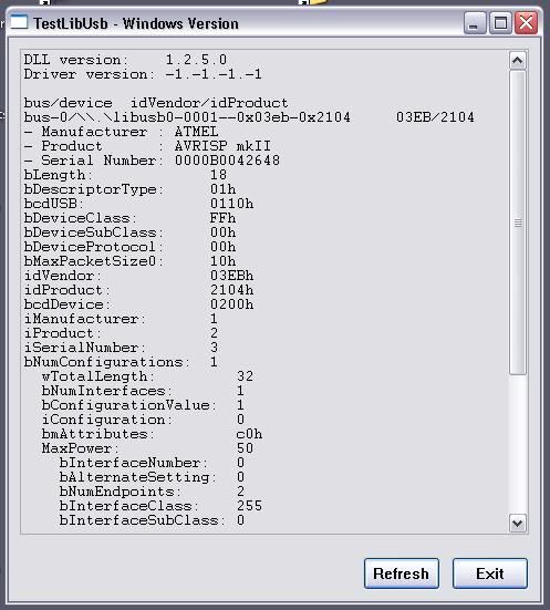
see example at bottom of this page). I tried this for the AVRISP, but with no success. Poking through the libusb start-menu group, I came across someting called "Test (Win) Program". This gave me the following screen:


I called AVRdude again, and instead of a port, I passed it the end of the serial number (as seen in the above page from the avrdude help) - and what do you know, I got a response!

Right, now what do I tell AVRdude to do to the chip? Well, the arduino bootloader page has a list of all the operations performed on a chip when the bootloader is burnt - I decided to use this as a template for what I needed to do.

The contents of \arduino-0018\hardware\Sanguino\boards.txt look like this:

##############################################################
sanguino.name=Sanguino

sanguino.upload.protocol=stk500
sanguino.upload.maximum_size=63488
sanguino.upload.speed=38400
sanguino.bootloader.low_fuses=0xFF
sanguino.bootloader.high_fuses=0xDC
sanguino.bootloader.extended_fuses=0xFD
sanguino.bootloader.path=atmega644p
sanguino.bootloader.file=ATmegaBOOT_644P.hex
sanguino.bootloader.unlock_bits=0x3F
sanguino.bootloader.lock_bits=0x0F
sanguino.build.mcu=atmega644p
sanguino.build.f_cpu=16000000L
sanguino.build.core=arduino
The ".bootloader" lines match the commands passed to the processor when programming. Looking in "Sanguino\bootloaders\atmega644p" lead me to the .hex file that is the bootloader. I moved this file to C:\avrdude\, as the version I installed here now worked (with the installation of libUSB).

Now that I had all the parts, I re-read the AVRdude help and composed a string that would perform all the operations that I needed: "avrdude -c avrispmkii -p m644p -P usb:48 -e -U lock:w:0x3F:m -U efuse:w:0xFD:m -U hfuse:w:0xDC:m -U lfuse:w:0xFF:m -U flash:w:ATmegaBOOT_644P.hex -U lock:w:0x0F:m"


Before trying to burn the bootloader, I used the -v switch to see if the ATmega 644P had a boot section. It does not, so the bootloader will be written to the flash.


It turns out that the string of commands was actually too long for the windows command prompt to handle in one go. I had to split the command up into single operations, which would help if something went wrong. I also added the -u switch to all the commands until I had finished writing the fuse bits - this stops AVRdude checking that the fuses are correct.


Here are the commands I used:


avrdude -c avrispmkii -p m644p -P usb48 -B 8 -u -e -U lock:w:0x3F:m -v
avrdude -c avrispmkii -p m644p -P usb48 -v
avrdude -c avrispmkii -p m644p -P usb48 -u -U efuse:w:0xFD:m -v
avrdude -c avrispmkii -p m644p -P usb48 -u -U hfuse:w:0xDC:m -v
avrdude -c avrispmkii -p m644p -P usb48 -u -U lfuse:w:0xFF:m -v
avrdude -c avrispmkii -p m644p -P usb48 -U flash:w:ATmegaBOOT_644P.hex -v
avrdude -c avrispmkii -p m644p -P usb48 -U lock:w:0x0F:m -v


The "-B 8" in the first line slows down the programmer by 8 microseconds. This is because the first time I tried to talk to the processor I got the error reported here. The second line is to check that the device now reports a correct signature, which it did.

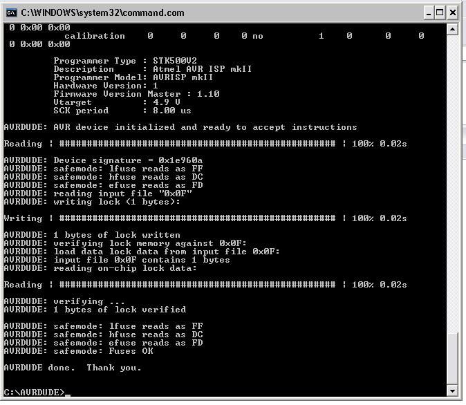
I called the commands in the order given above, and was greeted with success after each one. Here is the avrdude output from the last operation:

I was overjoyed that it worked - so much trouble for about 6 kb of data!

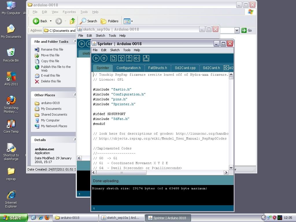
Now to see if it worked. I had downloaded and played with sprinter already, so I loaded it up into Arduino and clicked the "verify" button. It seemed to compile ok, so I clicked "upload".

After an antagonising wait:


It uploaded OK! The bootloader was a success, and now I can program firmware to the board via the USB connection!

For some reason, Reprap host has now stopped working. I think it is to do with the comms being interrupted by something that I recently installed. I went off and grabbed version 0025 of replicatorG, because it was the first alternative that came to mind.

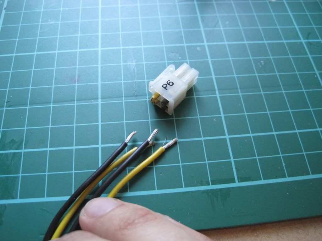
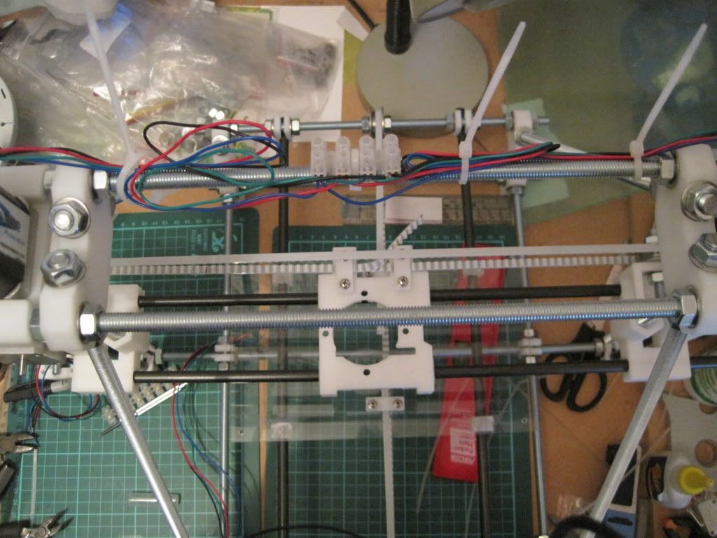
I connected everything up (Z-axis plugged in, PSU turned on and connected, USB lead to Bbernard), set ReplicatorG to use "klimentkip" as the communication protocol and told it to connect. After a short wait, I had a connection and everything was talking. I opened the control panel and asked the Z to move:


It went the wrong way. And only did it once before I have to reset the connection, but I'm sure I can fix these - in fact I have already inverted the Z-axis in the firmware and re-uploaded - Easy!

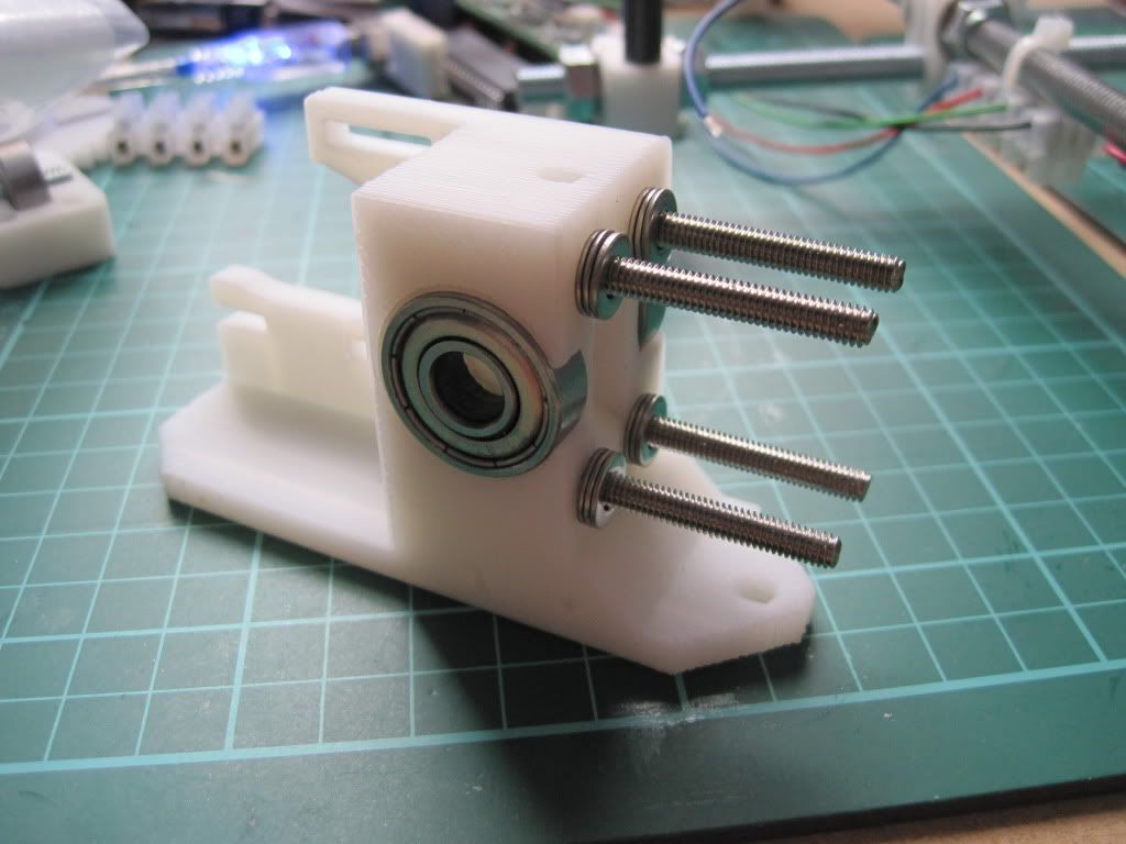
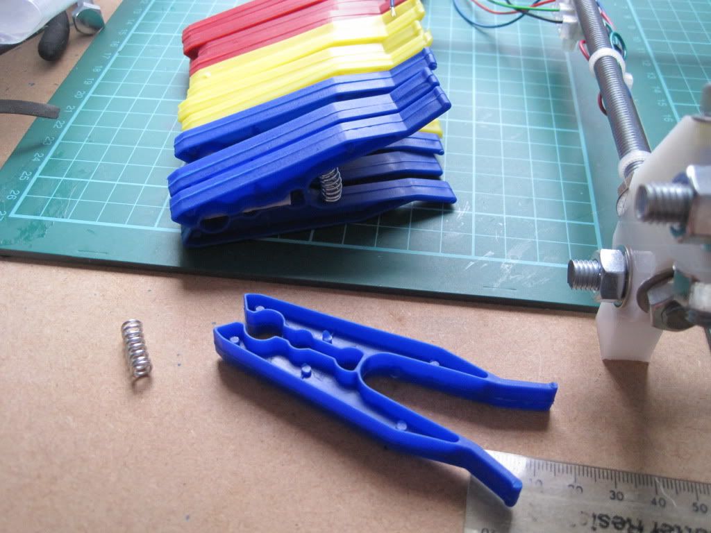
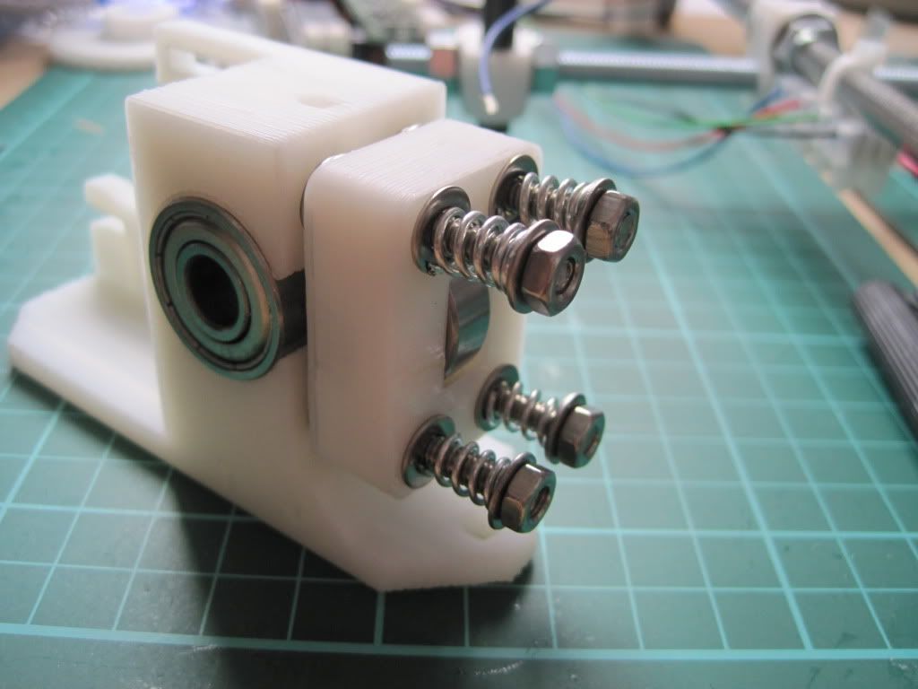
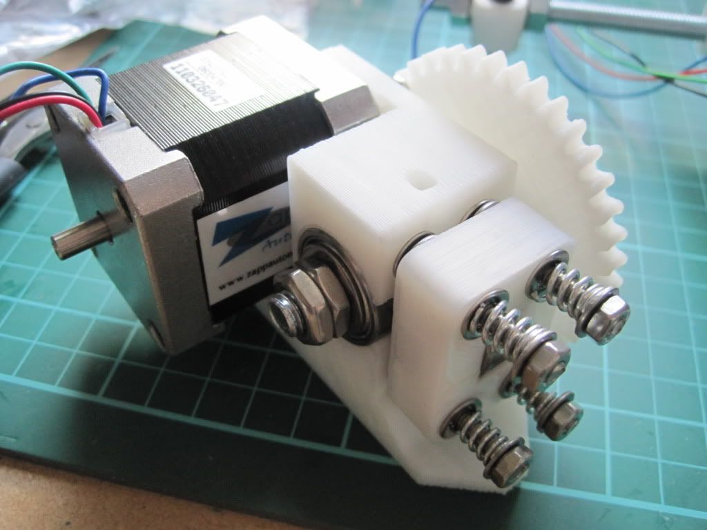
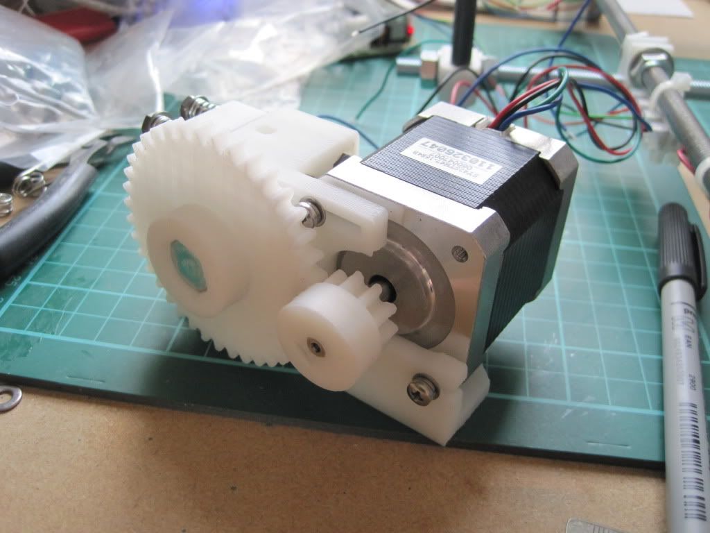
Next up - Building the extruder.

Sunday 11 September 2011

Chapter 16 - In which I seize power from the bin-men.

I had initially planned to pick up an Xbox 360 power supply to drive my machine, but it has come to light recently that they aren't too good when it comes to instantaneous loading. I decided to look around for something else.

I had already build the sanguiniololu board with the screw terminals and 5V regulator fitted, rather than the ATX parts. It is believed that the 5v line on ATX power supplies isn't as smooth as it could be. Still, I figured that I could use the 12v output from a similar supply and feed that into the regulator. That should supply smooth(er) 5v to the low power side, and 12v to the high side without a massively high voltage on the inputs.

It just so happened that work was in the process of throwing out a load of old IT equipment. I raided the waste electricals skip and came away with a couple of (hopefully) identical ATX power supplies. They're rated to 185 watts max, and can deliver 10A over the 12 volt line, which should be enough to get started with. I will run the machine from one, and perhaps use the other to power the heated bed, when I build one.


The reprap wiki has a page on using PC power supplies. ATX supplies have a power sensing circuit, and so to make it work I took a section of paperclip and bent it:


I used a fairly thick one to keep the resistance down. It links the green "power sense" pin to a black ground pin, thus turning the supply on.


This is a temporary solution - I will put in a proper switch at a later date, along with tidying up the extraneous wiring.

I took the high-current ATX-4 connector, and took (cut) off the plug. I stripped the ends and twisted the yellows (+12v) and blacks (ground) together. They will go into the screw terminals.


Lastly I stared to wire up the motors. I used some terminal block on the top rods to link the Z motors in parallel. I twisted the ends of the motor cables together, and fed them into one side of the terminal block. The other side is fitted with cabling that runs down the side of the frame vertex to the back-left of the machine, where the electronics will live.


I'm using "amp" insulation-displacement plugs to connect the motors etc to the PCB.


I borrowed an "amp-gun" criming tool, and crimped the cables into the plug.


To connect the motors to the board, the wires to each coil have to be next to each other. I checked the datasheet for my motors, and put the black and green together, and the red and blue. Lastly I used a CD marker to label the plug "Z".

Next up: that pesky bootloader.