It seems that although the firmware can be downloaded to the board via the USB cable, the processor has to have a bootloader burnt to it first in order to accept the download. This tripped me up a little, as the small amount of chips I've programmed in the past have only needed a single step. Also I came across this by accident while browsing the forums - I hadn't seen the requirement for a bootloader anywhere else.
There's now a good tutorial up on how to use an Arduino as an in-system-programmer (ISP) to burn the bootloader here, but I don't have an Arduino. (Ironically if I did, I would have known all about bootloaders...)
One of the recommendations on the forums is to use a USBtinyISP as the programmer. They're available on ebay but from Hong Kong and China, so shipping times are fairly long and I'm feeling impatient. Another recommendation from the same thread is to use a parallel programmer. These can be made from an existing parallel printer cable/adaptor and some resistors. It looked fairly easy to make, and I was heading to Maplin anyway to get the cable for the rest of the printer so I picked up the required resistors. I searched fruitlessly for a parallel cable at home, and eventually begged an old one from my Dad.
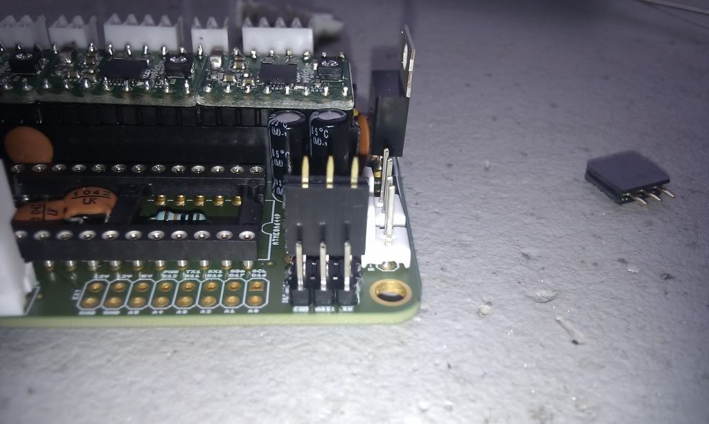
The first thing to do was to add the ICSP header to my Sanguiniololu. I hadn't fitted it as I had believed it was for expansion etc. I used leftover male pin headers from the main build to make the header, and the female sides will make the plug. (Today's photography comes courtesy of my phone - please excuse the poor shots!)
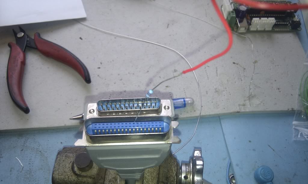
Next I used a multimeter to buzz out the cable. I had considered cutting the plug open, but it is moulded on and would have been very difficult to get apart. Instead I decided to solder onto the other end of the cable. This gives an additional benefit: since Bernard doesn't have a parallel port, I will be programming the bootloader from my main Pc. The long run of cable will give me some much-needed reach from behind my Pc to some clear workspace.
Curiously the PC-end of the cable has 25 pins, whilst the printer-end has 36. I used the meter to determine which pin went where:
PC end Printer end
Pin # 1 1
2 2
11 11
16 31
18 19
I used a very small soldering iron to attach the resistors directly to the spring-terminals in the plug.
At only 5 wires, it was simple enough to make. I used red wire to indicate pin 1 on the board-end plug.
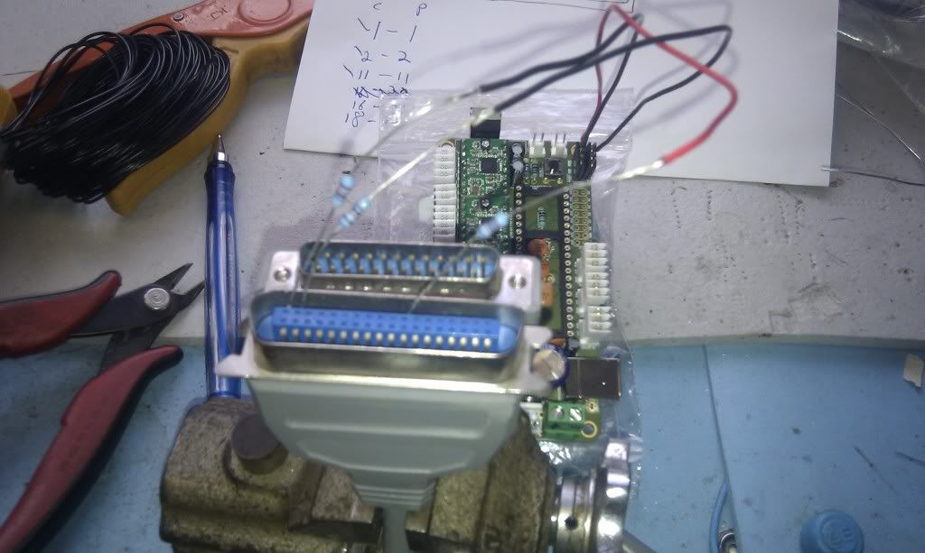
The board-end plug completed. I buzzed-out all the lines as I went, and it all looks good.
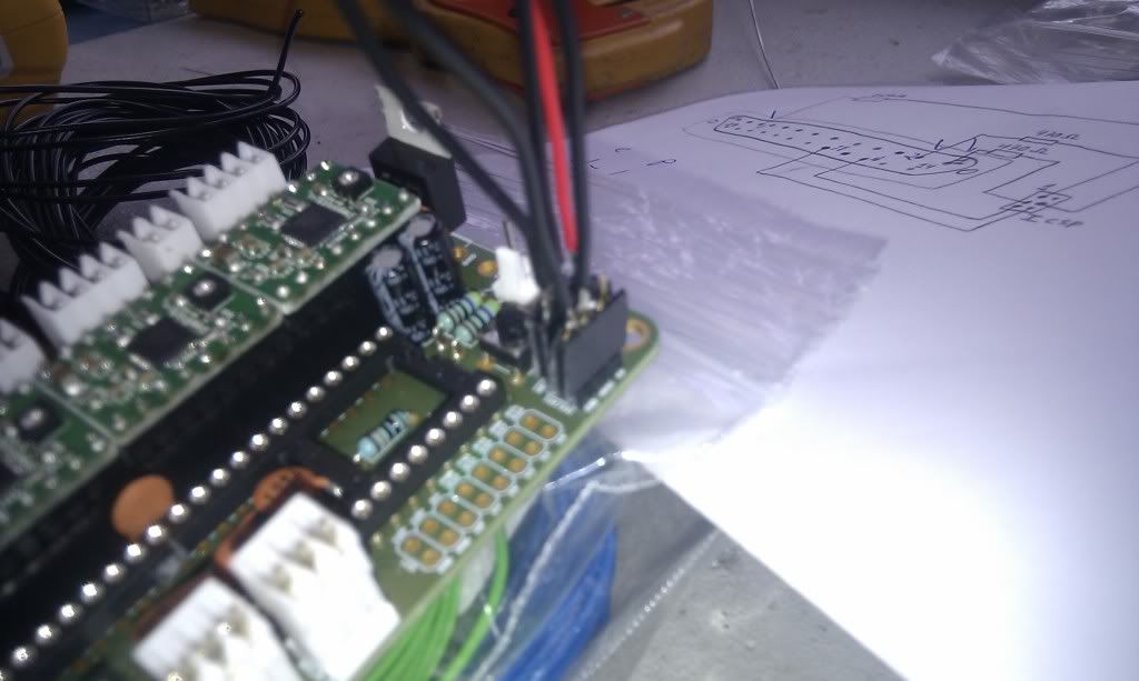
So, I now have the world's most fragile programmer. The solder joints to the printer-end plug are very small, and won't hold up to much handling, but I think I should only need to use this ISP once......
Might add cable ties and judicious amounts of hot-glue later to firm everything up.
Next up - Can I burn a bootloader with a makeshift programmer? We'll find out.....
No comments:
Post a Comment