Thursday, 20 October 2011

Chapter 21 - In which I (finally) start the long-awaited hot-end post!

Firstly let me say that progress has been made recently - quite a lot in fact. But that's for a later post. For now, lets catch up on the last couple of weeks/months as I set out to solve the conundrum of the hot end....

For those of you who may have missed my first post, I started out on this project with no idea of what to use for the hot end, or how to make one. The tools in my garage are pretty much limited to a powerdrill and an electric screwdriver! I decided to build a hot end design that I could realistically make in my garage, without the use of a lathe, pillar drill or any other fancy machinery.

The hot end basically consists of several parts: the nozzle, the heater barrel, the thermal barrier, a heater block, a heater, and a temperature sensor.

The Prusa CAD model on the wiki includes a basic hot end setup. It uses a 0.6mm MIG welding tip as the nozzle/heater barrel, although the details of the heater are left off. MIG tips are not expensive, and so I picked up a 10-pack from ebay:
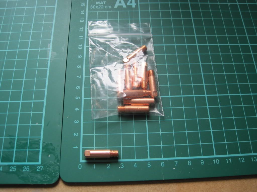
They have a 0.6mm hole straight through the length of the body, and are threaded to M6.
The hole in the bottom of wade's extruder body is 16mm, so I bought some 16mm outer diameter PTFE rod. This will act as the thermal barrier between the hot end and the extruder body.


Some designs use a PEEK thermal break, and I happened across some for a good price on ebay. I've not used it yet.
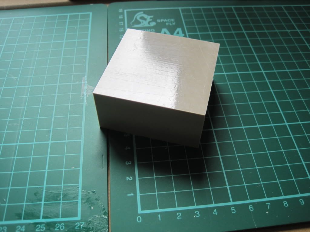

Now for the heater block. This is the one part that really stumped me. I didn't really fancy trying to get hold of Nichrome wire and wrapping the nozzle in it, so I decided to use a block of some sort. I figured that without a drill press or pillar drill, there was no way I could accurately machine one for myself, so I spent a long long time searching for something suitable and pre-made.

I came across these and these on screwfix. they are for bonding wire to earthing rods, but would perform well here as they are brass and have a clamp built in to hold them onto the nozzle. The drawback is that they would need another hole of some sorts drilled into them for the heating resistor, and another for the sensor.

Whilst browsing ebay, I came across car battery terminals. They looked spot on - a larger hole for fitting the nozzle through, and a smaller one at right-angles for the heater. After another long search, I found the smallest  ones I could. They are for (older?) Nissans, that use smaller terminals on their batteries, and in particular the negative terminal as it is slightly smaller than the positive. I bought a couple from ECS.
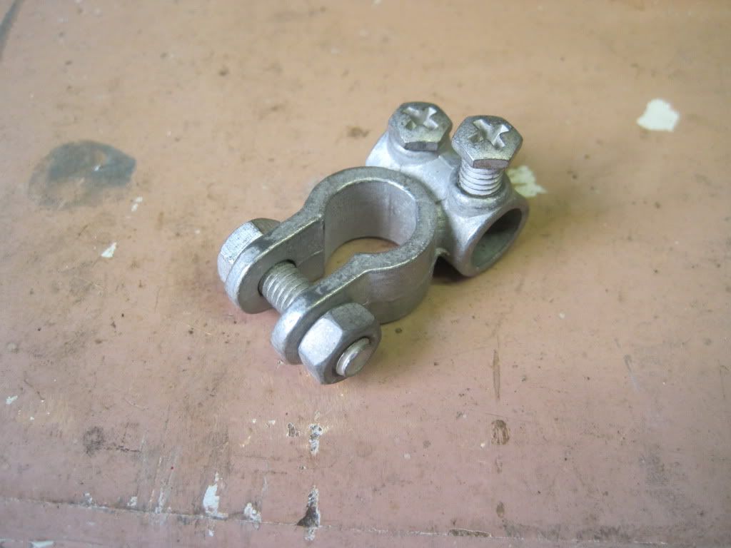

The last problem to solve was how to bulk out the ~6mm diameter MIG nozzle to the ~12 internal diameter of the clamp. Eventually I settled on using a series of copper pipes, cut into sleeves of ascending diameters. I would also use this method to fit the resistor into the 10mm cable hole in the clamp.

I 3D modeled the whole assembly, and fitted it to the X carriage and wades parts:
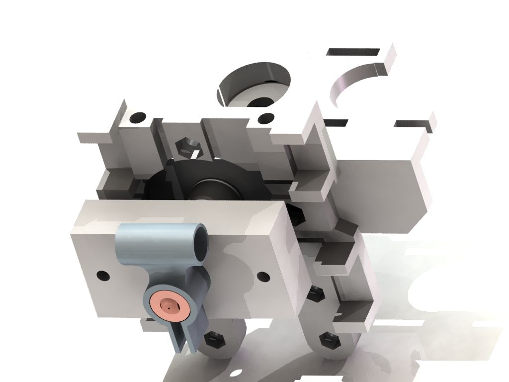

The large rectangle above the clamp is the PEEK block, cut down. This would have had the thread cut into it to hold the nozzle, and have been held to the assembly with long bolts that also held the extruder body to the carriage. The more I thought about it, the more I worried that coupling the extrusion force directly to the carriage like this would snap the carriage. Eventually I dropped the PEEK, and decided to just use PTFE, and couple it via the screwholes in the extruder body.

Blogging about it seems to trivialise the process a little. I seem to recall spending ages thinking, doodling and searching, trying to find something that would work right, and the struggling to fit it all together in my head.

Once I had settled on the design, I started to make bits. I used CAD to make a drawing of all the parts that I had to fabricate. (If anyone wants to replicate this madness, I am happy to post/supply my drawings and models. I might upload to the wiki if this actually works as intended!)
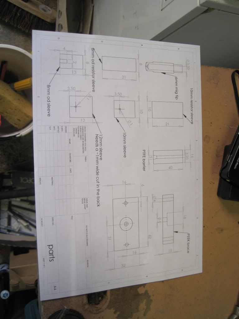

Here are the parts laid out. The copper pipe is some scrap bits that I collected, in 3 sizes.
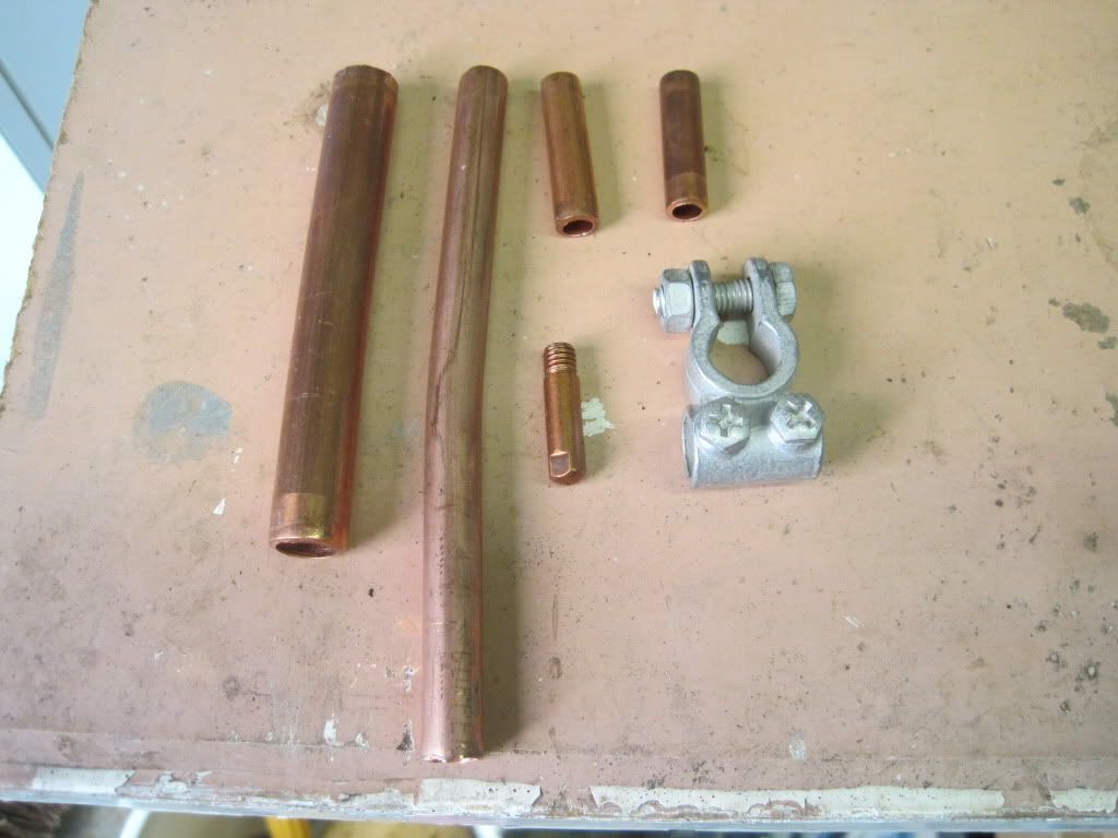

Fast forward through lots of sawing, and drilling pipe to expand the diameters a bit:
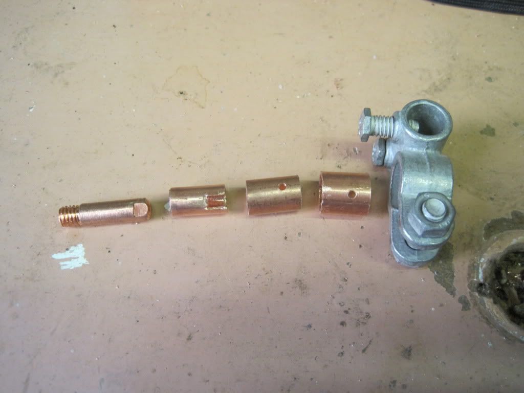

I drilled the MIG tip out to 3mm internal diameter, as deep as I dared. I had intended to drill it progressively, but the hammer action came on on the drill by accident and snapped the 1.5mm bit I was using, so I started again and just went to full width from the start - it was hard work! The sleeves have holes and slots in them, such that the sensor can reach right though the sleeves and be held captive against the flats on the tip. the tip and sleeves 1 are such a tight fit that I had to turn down the outside of the tip with a file. Sleeve 3 is too large in diameter, so I cut a slot in the back and reduced the diameter (in a manner that my sister - a jeweller - would have cringed at). I also cut down the pipe for sleeving the resistor:
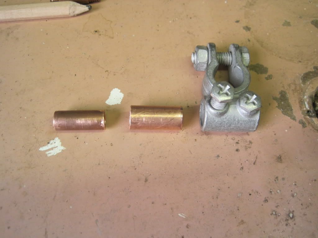

The next job was the PTFE barrier. Shouldn't be too hard, right?
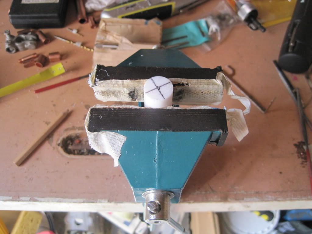

Turns out, it was very difficult. This is the only part that really needed a machine tool. It was very difficult to get the hole straight down the middle. I actually succeeded first time, but then as I tried to drill the counterbore for the thread, the bit "grabbed" too much and went way too deep, ruining the part. The two subsequent tries were as bad, or worse:
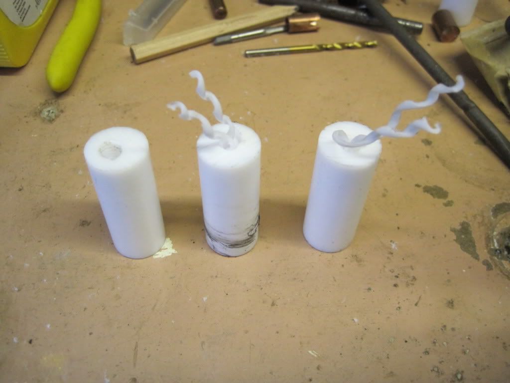

I encountered one of the lowest points so far on the project. I just couldn't do this bit, no matter how hard I tried. I had seen somewhere the notion that a reprap should be buildable in the garage, with no special tools. I know that I am pushing that definition a long way by having almost nothing in terms of tooling, but the longer I went on the more determined I had been to make the entire printer without machine tools. I thought that if I could invent a design that didn't use anything  more than a drill, maybe I had something to add to the reprap world. It looked like I just couldn't do it.

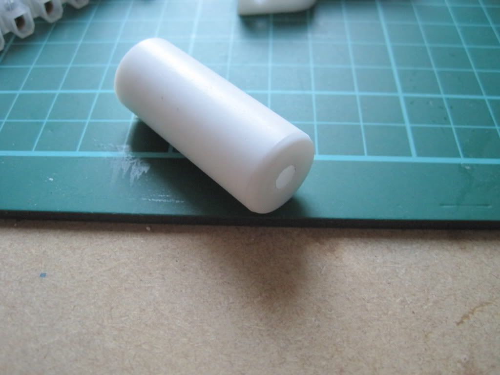
Eventually I decided that I had come too far to give up. I'm really interested in printing afterall, and taking this hardcore home-fabbing approach wasn't getting me any closer to my goal. Grudgingly I set aside the idea of a machine tool-free hot end, and took the remaining PTFE into work. Less than 10 minutes on the lathe produced a lovely looking thermal barrier:

I took it home and tapped it to M6:
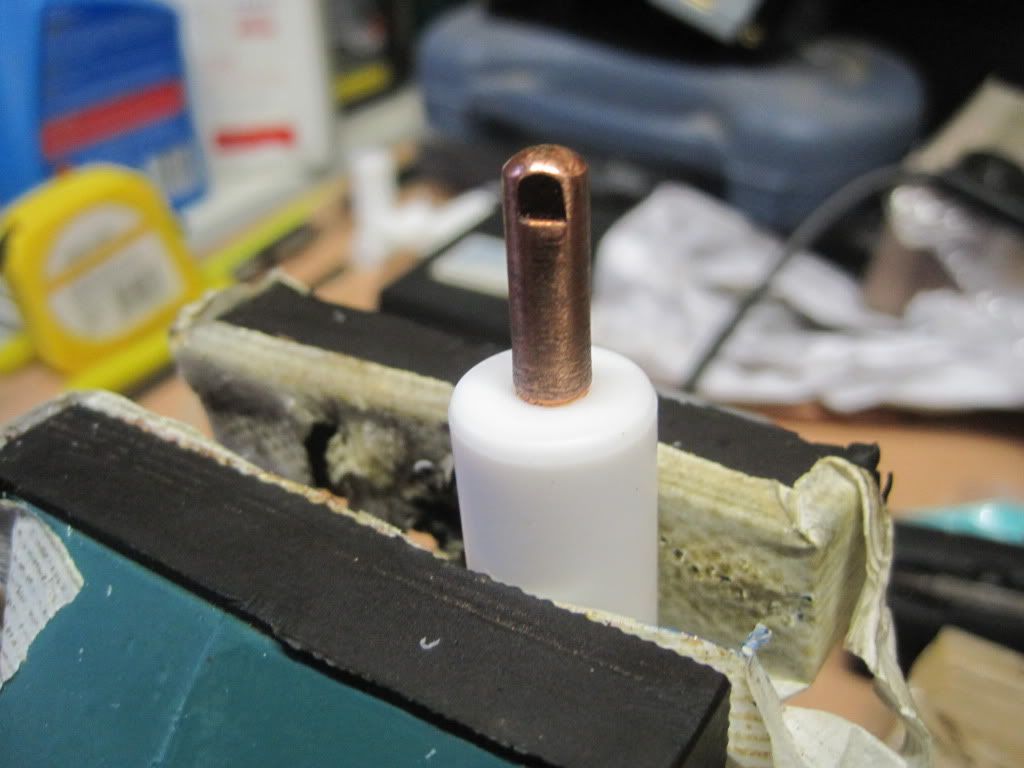

I used heat-sink compound between the layers of sleeves to remove the air gaps. It's not as conductive as metal is, but much much more so than air. I made sure the coating was very thin, just enough to eliminate any air gaps. I tapped the sleeves together with a hammer, using a two blocks of wood to protect the ends.


Here is the nozzle completed:
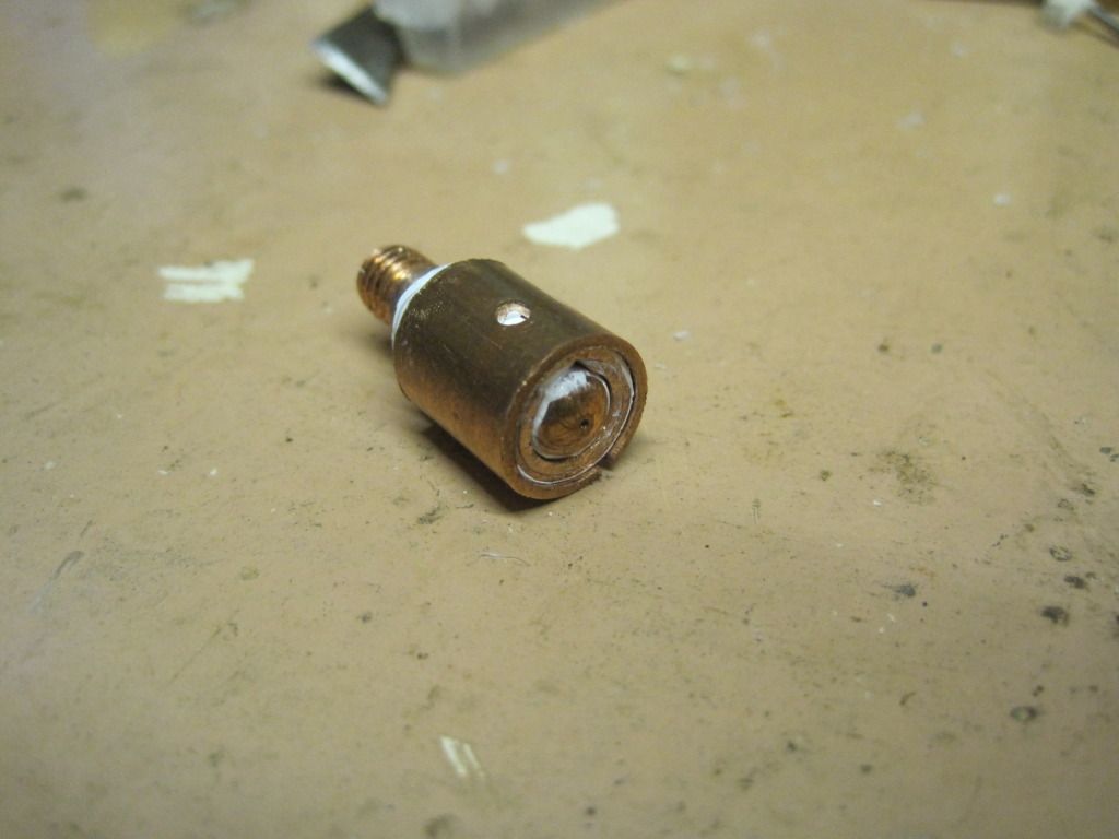

It feels fairly solid, with the exception of the outer sleeve which has to stay loose until it is clamped.

So that's my hot-end. Next up: all the fun of mounting the extruder, hot end and other stuff!

Sunday, 16 October 2011

Chapter 20 - In which problems are rectified, and I make a temperature sensor the professional way

Its been a while since my last post. This is due to having had a week away in Scotland, but also due to progress being slow. I have however made some progress.

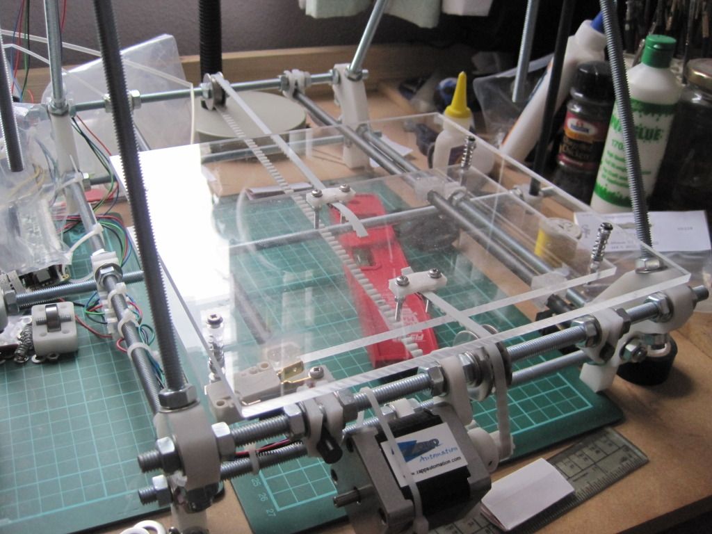
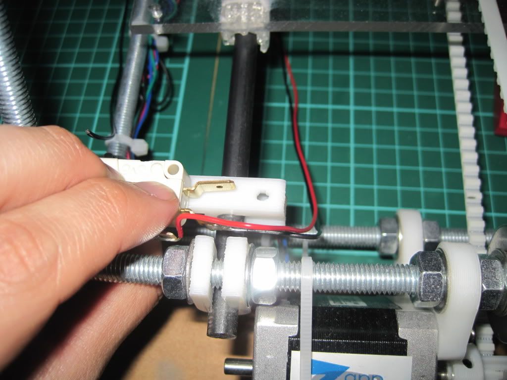
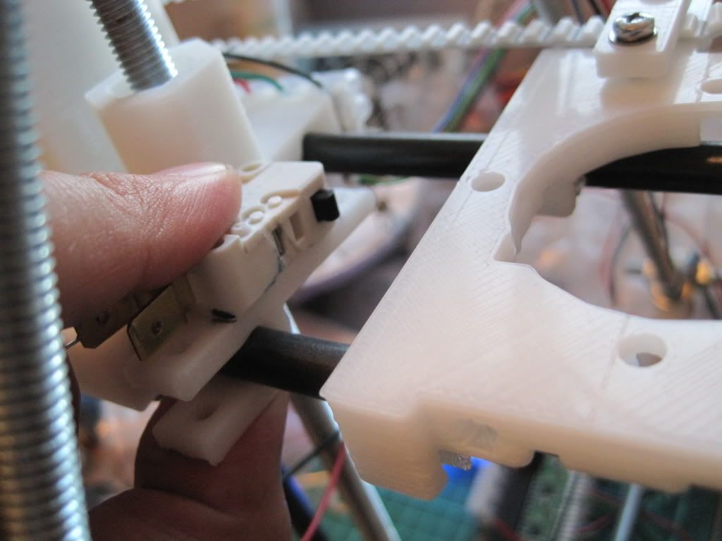
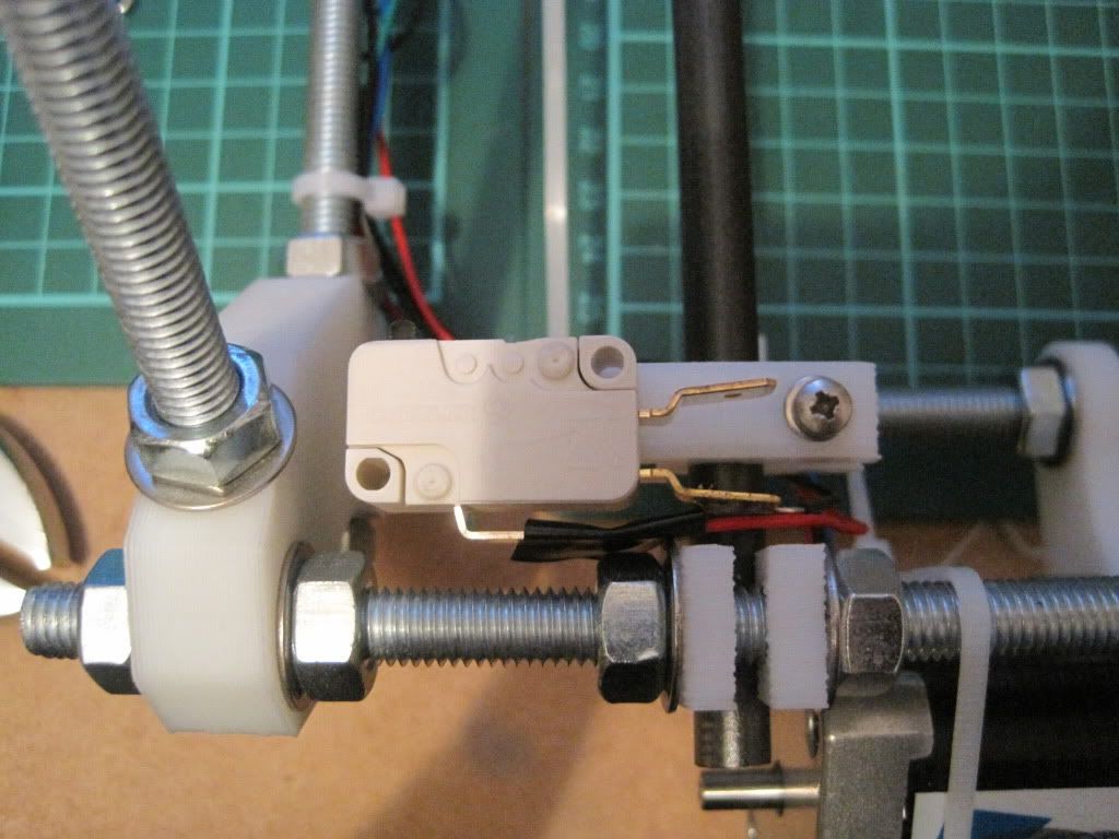
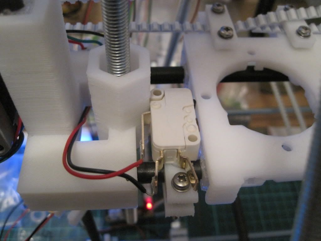
Firstly I changed the angle of the X-axis endstop. I had test-fitted the extruder body, and found the endstop was in the way. There is a conveniently provided little square protrusion on the side of the carriage, and the contact of the realigned endstop sits nicely on it.

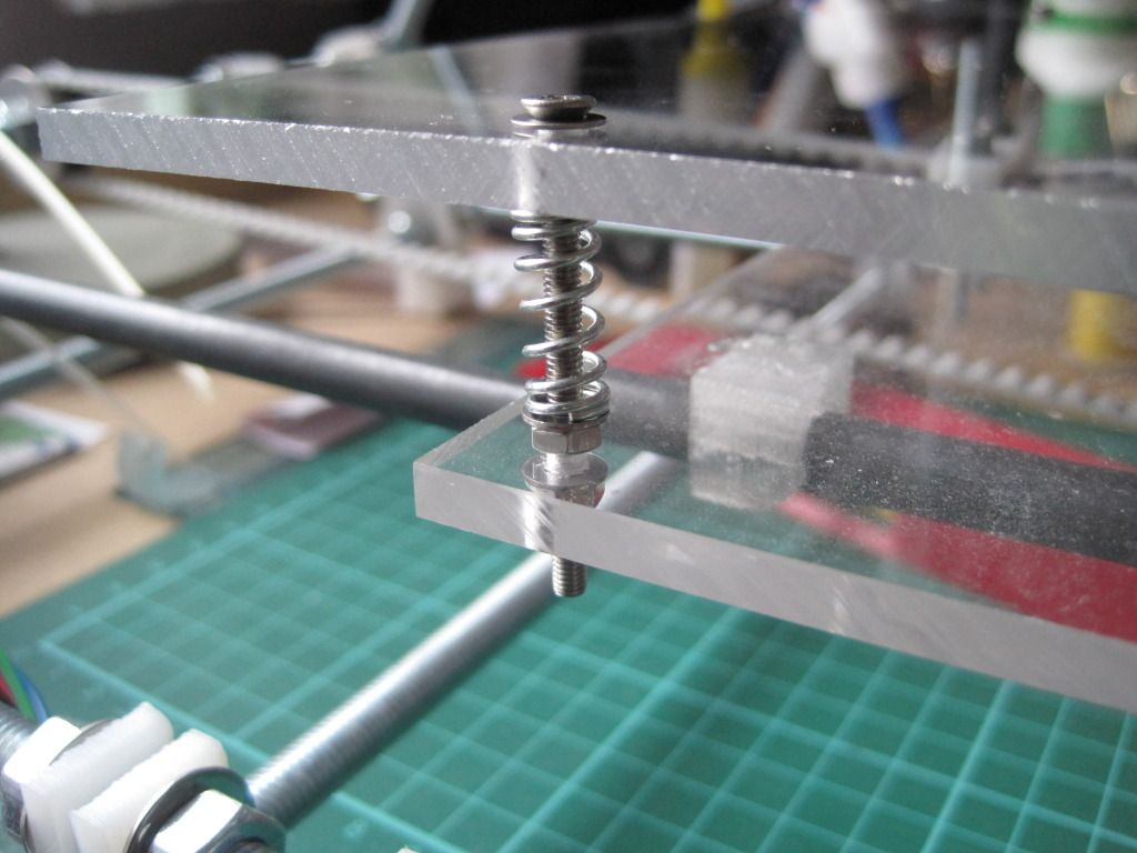
I then proceeded to fit the print bed. I had spotted this post on the forum, and decided to make the upgrade now rather than later. I had also got lots of peg springs just waiting for a use. I have used countersunk screws to mount the bed, but only because they were the only ones I could get with the correct length. There are washers under the heads to prevent the screws pulling into the bed and cracking it.


The bed is fairly level as it is, but I may tighten up the nuts to compress the springs, making the bed firmer and less prone to wobble. This has the added advantage of giving some extra Z height.


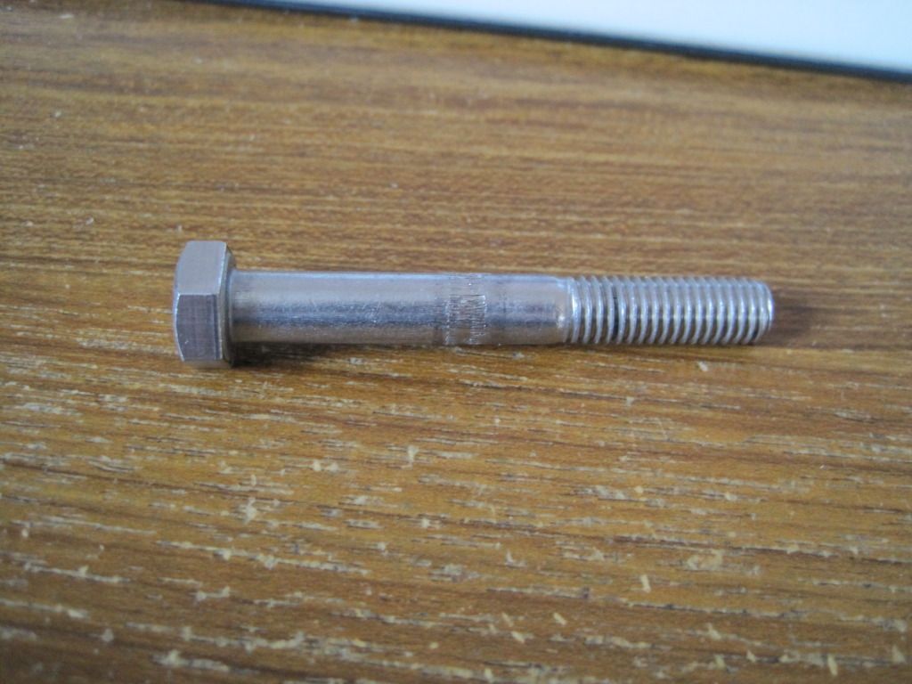
I had ordered some replacement bolts to hobb, as the previous one was too narrow. Once they turned up, I spent an evening in the garage attempting to hobb one of them. It was much harder going than the previous bolt - maybe these are made of something harder? I was also trying to hobb with an M6 tap as opposed to an M3, to give bigger teeth on the bolt. I just couldn't get it to cut the teeth correctly, and it left an un-cut section in the middle of the bolt. I ended up getting very frustrated with it, and walked away trying to decide how to go about making one properly.

I came back to it a week or so later, and had a proper look in the daylight. The hobbing down one side looked pretty good, and fairly even. I figured that I could probably space the bolt such that the good section was doing the driving.


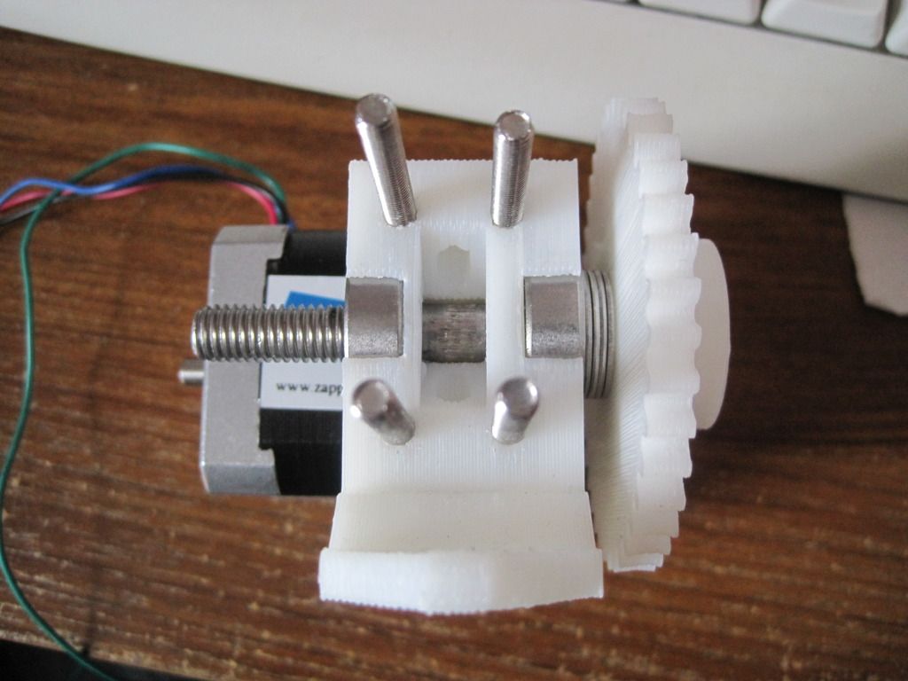
I put the extruder back together, and was pleasantly surprised to find that the good section was in the correct place already. Better than that, it had enough grip to drive feedstock without the idler in place! Whilst working on the extruder, I also moved the motor and fitted the bolts that will mount the extruder to the X-carriage. I reassembled the extruder and idler, and repositioned the motor to get the best interface between the gears.


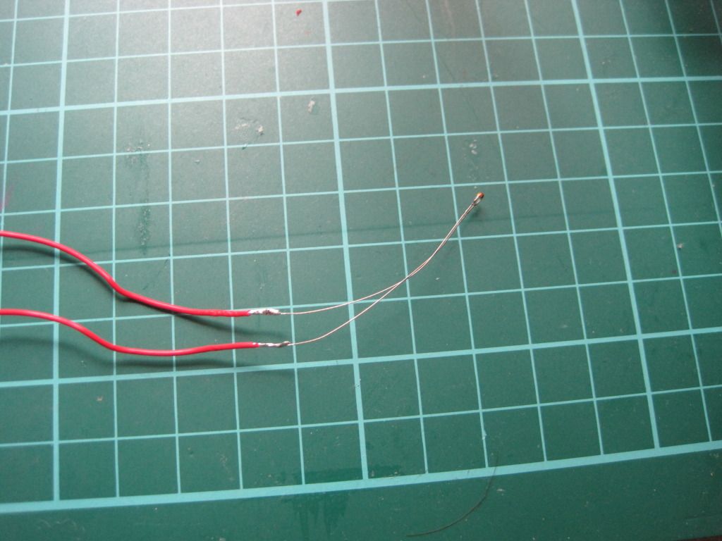
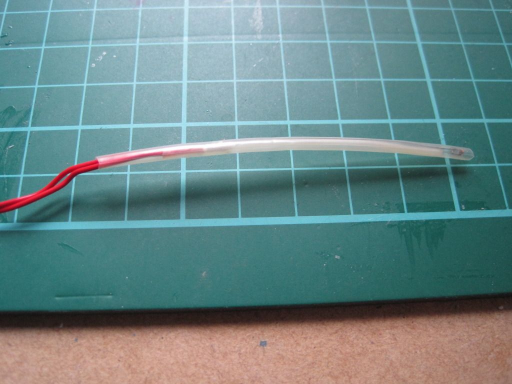
I also had the time to make up the hot-end temperature sensor. I constructed this in a similar manner to how professional temperature sensors are made. Firstly I soldered the ends to the stripped ends of the PTFE wire:


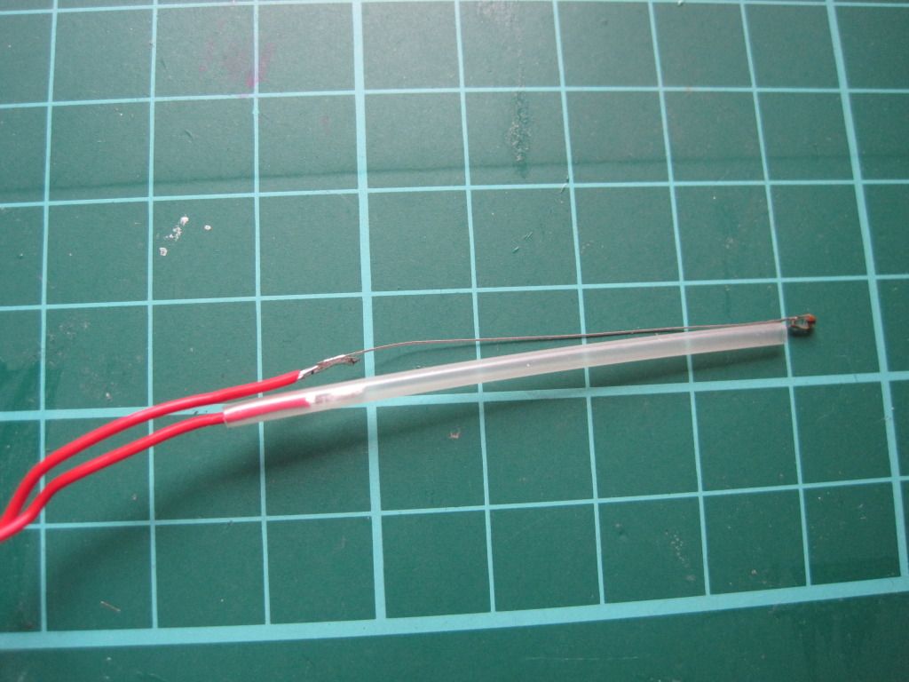
I then used high-temperature heat-shrink sleeving to insulate one leg, all the way from the small joint at the thermistor head to past the solder join:


I shrunk the sleeving with the kind help of my girlfriend and her crafting hot air gun:


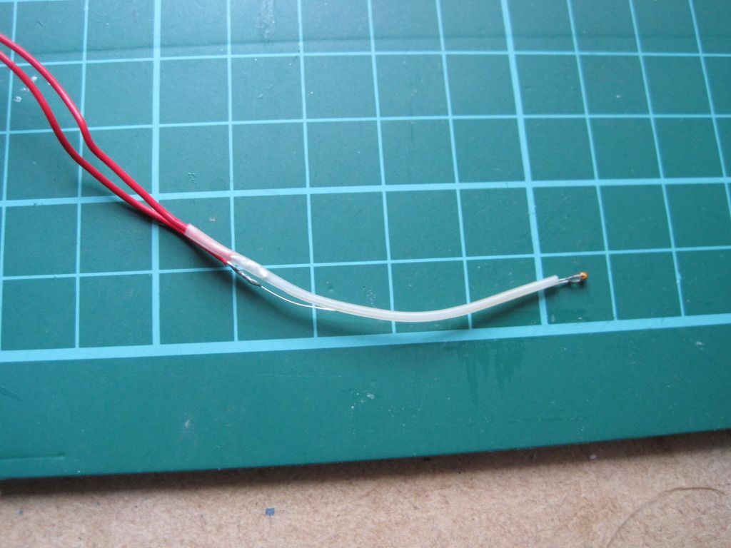
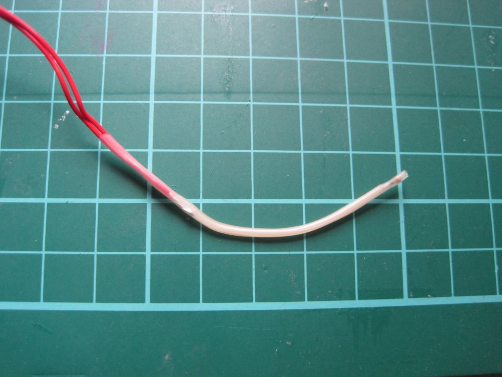
I then used a larger diameter piece of the same sleeving to cover the entire assembly, from a point past the thermistor head to past the remaining soldered joint.


Lastly I trimmed the overhanging sleeving close to the bead. This assembly method should provide a robust and short circuit-free sensor for the hot end.

And Thats all the I've managed to achieve. Next up: The long-awaited hot-end post?

Friday, 30 September 2011

Chapter 19 - In which there is life!

I've been spending a lot of time recently working on the hot-end, but I'm saving the writeup until I have it completed and can make a whole post.

In the meantime, I've made small amounts of progress in other areas.

I have completed the wiring of the stepper motors for the axes. I wired them all the same, and consequently had to invert the direction in the firmware. I have also resisted cutting down the motor cables for any of the motors. I feel like I might need them longer later, in case I want to swap a motor or something. I realise this is unlikely. I'll cut them down later, if I can get the courage to. In the meantime, the excess cable is neatly bundled with the motors, or on the frame.

Once I had all the motors wired up, I fired up ReplicatorG to move the axes and check the direction was correct. I encountered a strange bug, wherein the axes wouldn't move properly under manual control, sometimes only moving a short distance, and other times moving in reverse. Also sometime multiple axes moved at once! I don't know if this will effect the operation of the machine when printing, but I didn't like it.

I went off and installed Pronterface instead. After the fun I had with sprinter, I was expecting to have some trouble with Pronterface, but was pleasantly surprised. The install guide is concise, but it works perfectly. Printerface needs almost no configuration, and is very quick - I like it! Comes with built in skienforge support too, which is nice. Infact I then went off and got Sfact too, as the pair seem to go together well (pronterface has some sfact-exclusive options).

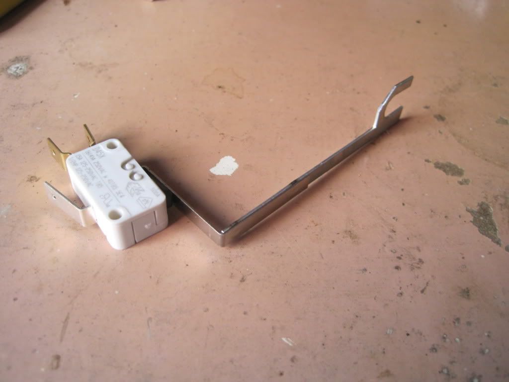
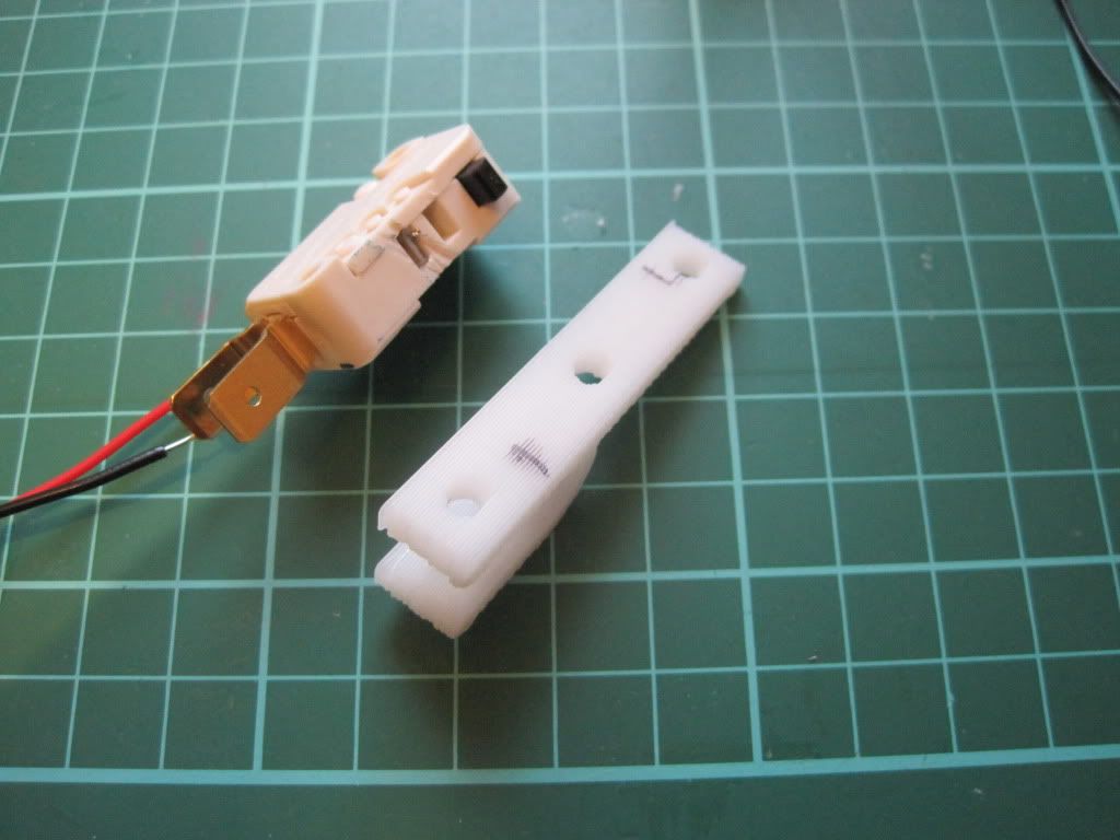
More recently I have added the endstops to the axes. I'm using microswitches, and they had arms on them:


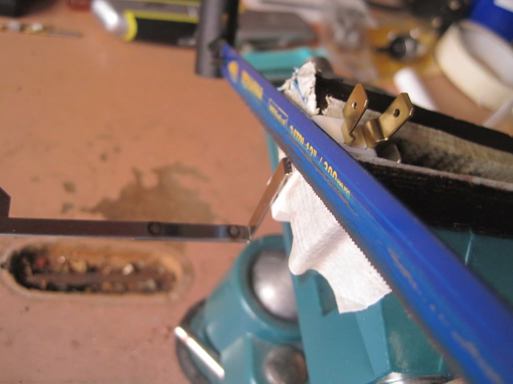
I popped them into the vice, and sawed off the arms - careful to avoid sawing off the switch!


I decided on locations for the endstops. They are configured as being at the minimum end of the axis in firmware, and so this translates to Y being at the front, the X being at the left, and the Z at the bottom. I played around with locations for a while before marking up the brackets.


I attached the endstops to the brackets with hot glue, as the screwholes were in the wrong places. Each bracket was then fitted to the axis with an M3x25 screw, with a couple of plain washers and a spring washer.  I added some insulating tape to the Y axis terminal, so that it didn't short to the frame.


Once the endstops were installed, I wired them to the plugs and routed the cables along the frame.

I powered on the machine, and tested the endstops. I moved the axis out a long way, and then told it to return. As it was moving I activated the switch. All 3 axes worked ok, stopping the moment the switch was pressed. I then told Pronterface to "Home" the axes. It was pretty scary to watch, as the axes drove themselves into the stops:


In other news, I ordered some filament from Faberdashery. When I tried to load it into the extruder, disaster struck! The hobbed section of my bolt is too narrow, and the filament is too rigid to come into contact with it, regardless of how much pressure is applied by the idler.

I have to hobb a new bolt. I have ordered some M8 by 60 shoulder bolts from ebay, and will hobb the shoulder with an M6 tap - if I can work out a way to do it.

Next up: not sure. Maybe the hot end.

Tuesday, 27 September 2011

Chapter 18 - In which my alternate spring source is validated

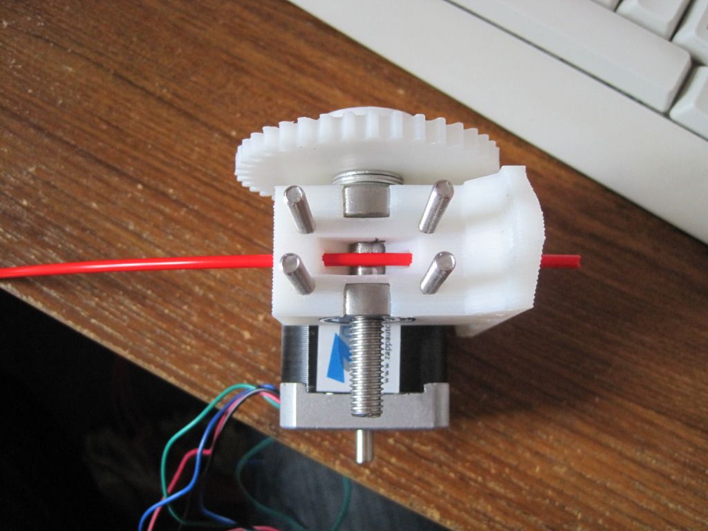
One quiet Sunday, I sat down to build my extruder. I had already hobbed the bolt, and so now only needed to build up the extruder body.

I had a little trouble fitting the bearings into the extruder body, but a little work with a file ensured that they sat flush:


I had a peice of threaded rod left over from cutting the frame bars down, so I cut it to 50mm and used it to mount the idler bearing. The bearing seems a little loose though, so I may have to change it out in the future.


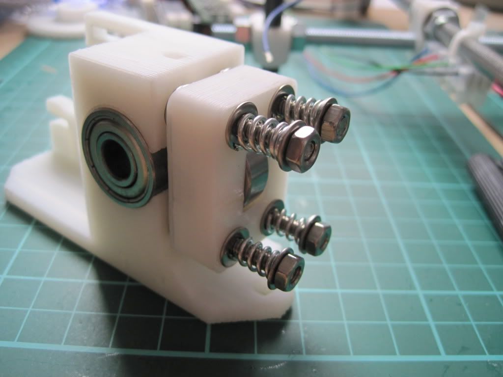
I fitted M4 by 50mm bolts through the extruder body, and fitted a pair of washers to each one. I had to file out the screw holes a little to make the bolts fit.


I fitted the idler block over the bolts - this was harder that I had thought it would be, due to having to keep the block square or the bolts would bind up.

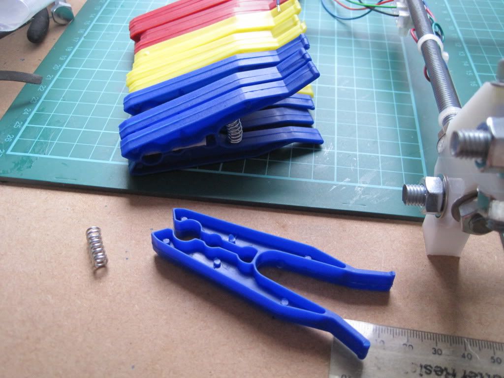
Now, time for the all important springs. As I mentioned here, I had found a source of springs in a certain shape of clothes peg. I had ordered some after scouring ebay for the right type. Unfortunately when they arrived they were the traditional, sideways-action spring type. I got in touch with the company, whoi were able to find some of the kind their listing showed. Lesson learned by me - some photos on ebay are for illustrative purposes only. Once I had the new, correct, pegs in hand, I set about de-springing them.


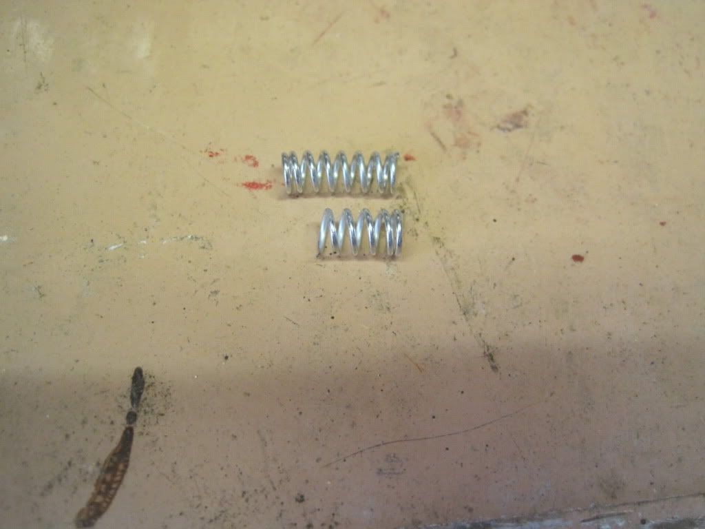
Having removed 4 springs, I was faced with another problem - they are too long for the bolts. After failing to compress them enough to get a nut onto the thread, I took them to the garage and took a hacksaw to them.  I cut them down to just the right length to allow them to be fastened on, with only a little compression.


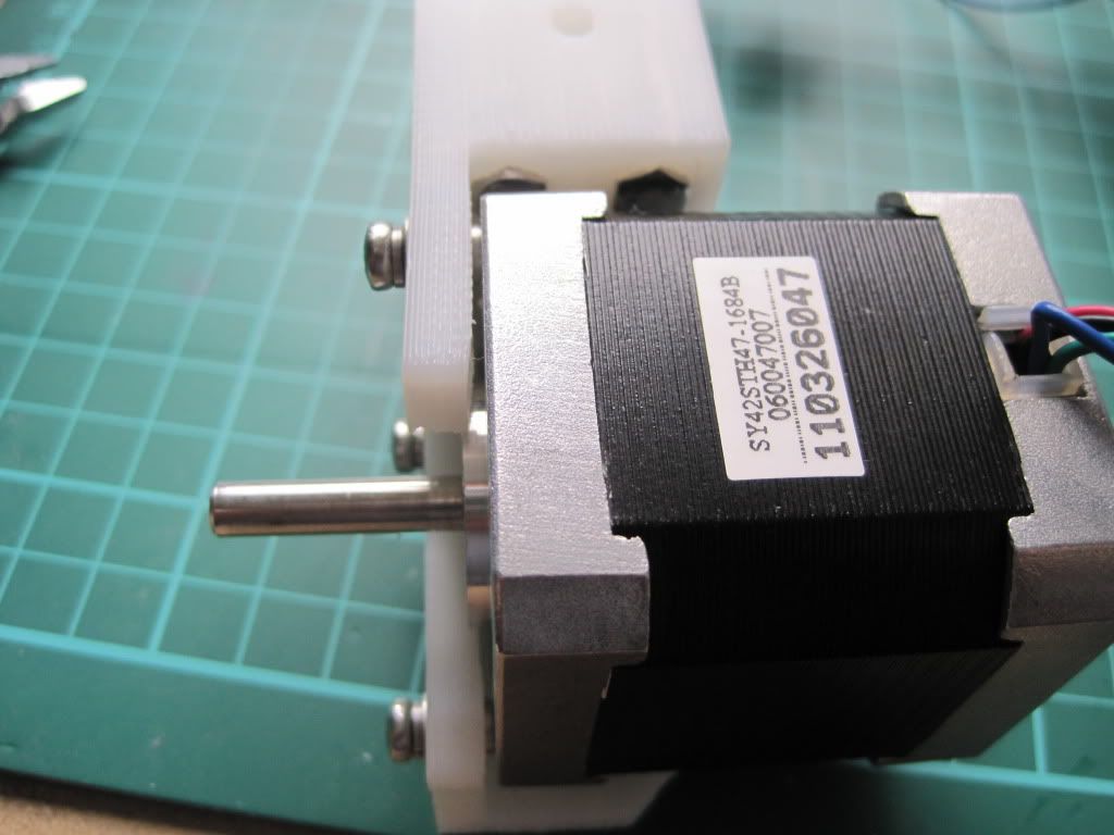
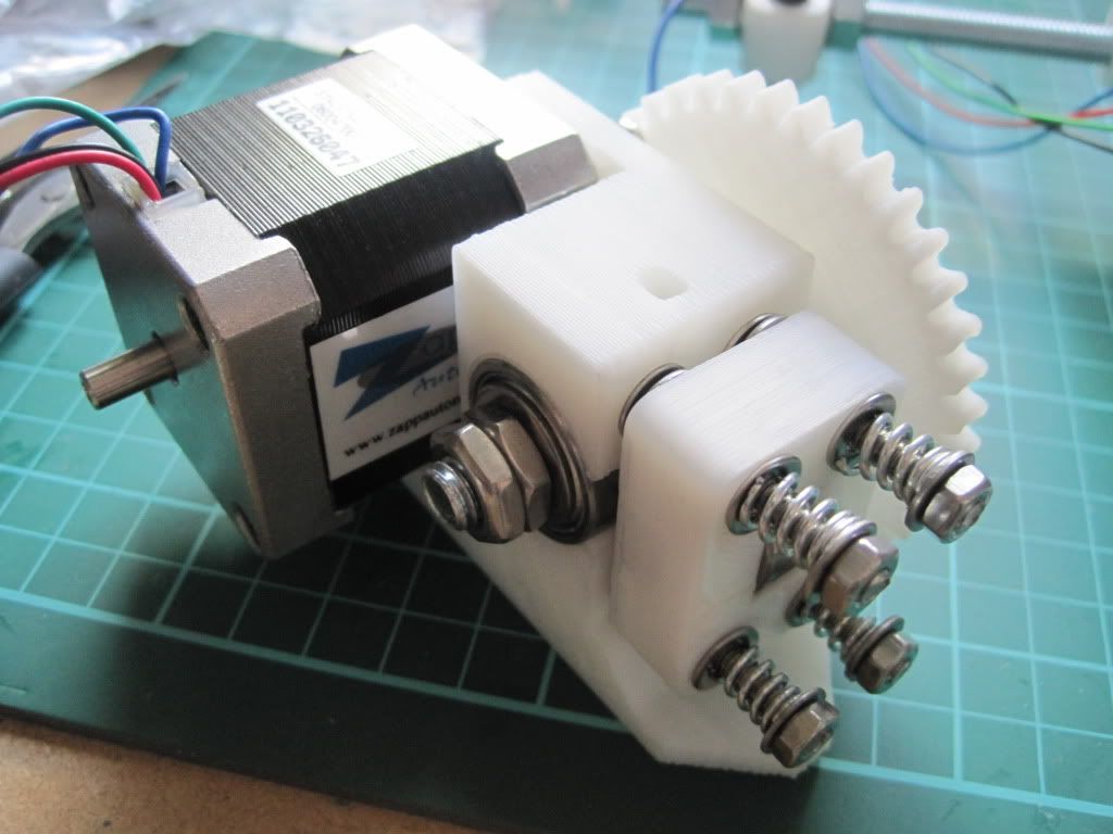
The motor mount on the extruder is thinner then that of the Y axis, so I though I could use the same trick of doubling-up the washers as I did on the x-end-motor. However, This made the Screw heads stick out too far, and they interfered with the gears. I opted for the solution below, with one set of spring washers between the motor and the extruder, and the other next to the screw heads:


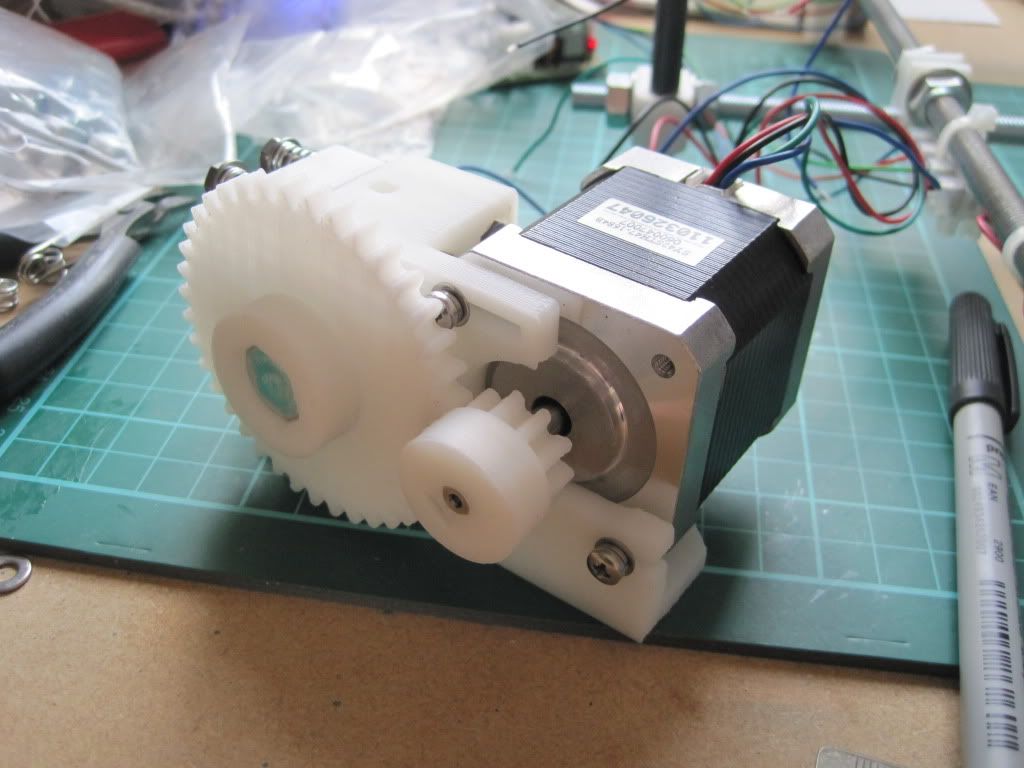
I fitted up the hobbed bot and large gear. I had to use 4 M8 washers to space the bolt correctly, because the hobbing had drifted to one side.


I had used a couple of M8 halfnuts that I found to hold the hobbed bolt in place, but have subsequently moved to one half nut and one full nut as I had problems getting the tension right and the locking tight enough.

Because of the extra washers spacing the big gear, I had to mount the small gear in reverse. This is actually suggested in some of the instructions, and won't cause any trouble due to the grub screw still being securely on the shaft.


Next up: talking to the machine

Thursday, 22 September 2011

Chapter 17 - In which I finally burn the bootloader

This bootloader business has really tripped me up. As I mentioned here, I built a parallel port programmer to burn the chip with. Having a quiet Saturday in hand, I set about programming the chip with the bootloader.

Since Bernard doesn't have a parallel port, I loaded Arduino 0018 onto my main machine, along with Sanguinio. I plugged in the prgrammer, connected my sanguiniololu to the USB port (installed the FTDI drivers etc) and ran Ardunio. I set the board type and COM port up, and then selected "Burn bootloader w/ parallal programmer" and sat back and watched it program.

Actually I sat back and watched it fail. I got the following error message:
avrdude: initialization failed, rc=-1
avrdude: Yikes!  Invalid device signature.
avrdude: Expected signature for ATMEGA644P is 1E 96 0A
avrdude: AVR device not responding
 ***failed;
avrdude: verification error, first mismatch at byte 0x0000
         0x3f != 0x00
avrdude: verification error; content mismatch

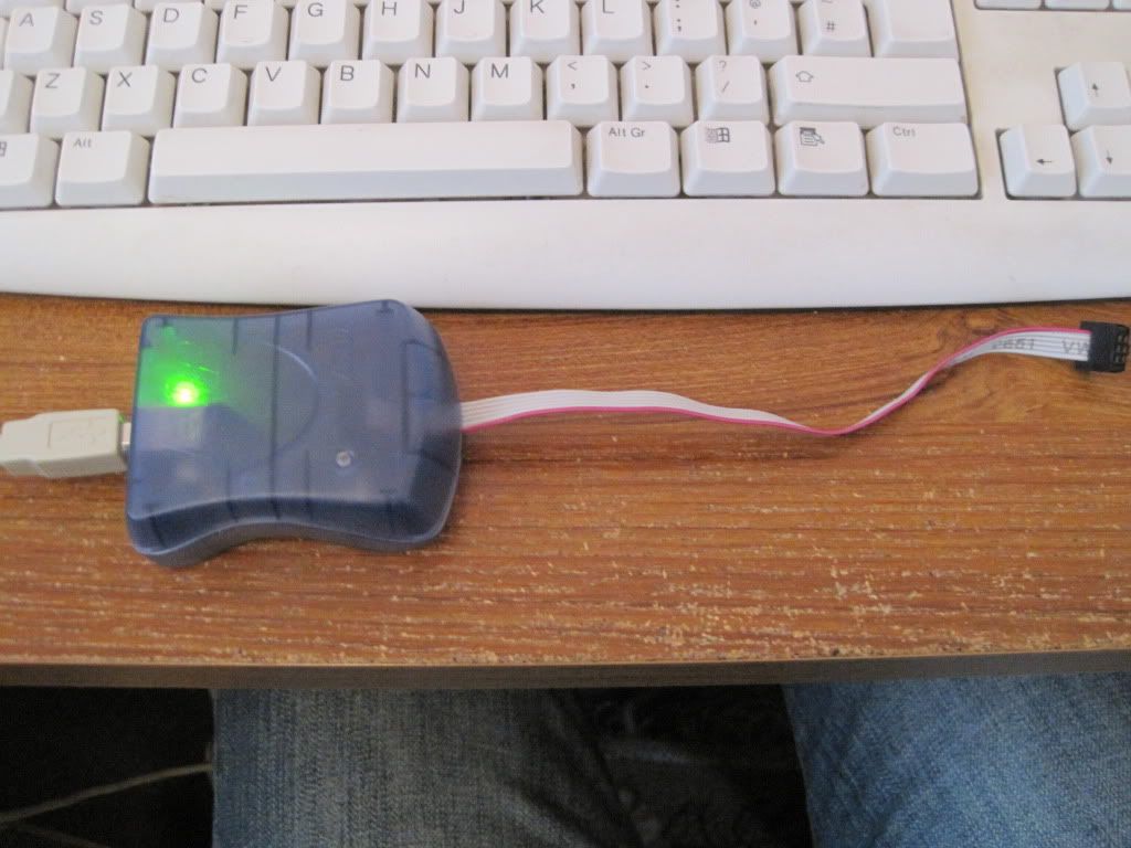
I tried a couple more times, and still got the same message. I decided to give up on the parallel programmer, and use an AVRISPMKII programmer that I had borrowed in case this happened:


I plugged it in and watched the computer try and locate some drivers fir it, but it failed. I went off to Atmel's website to download the software I needed - AVRstudio 5. 600megs and some time later I tried to install it, and was once again met with failure: AVRstudio needs win XP Service Pack 3, which is not installed on my machine.

I transferred the setup to Bernard and installed it there, along with its prerequsities, extras and the Jungo USB driver (which I felt was probably the part I really needed). I plugged in the programmer, and watched it install the drivers correctly this time. I rebooted, fired up Arduino again and hit "Burn bootloader w/ AVRIsPMKII". Did it work this time?

No.

Turns out Ardunio couldn't find the programmer, despite the software and drivers being present. I almost gave up at this point. It shouldn't be this hard to load a tiny file onto a chip! Instead of giving up totally, I started to scour the net, searching for anything useful to my situation.

I read the Arduino site, and found info on the preferences and programmers files. I changed some settings, tried again and failed again.

I looked up avrdude, the program used by Arduino to program the bootloader, and read all of the documentation. I tried to call Arduino's copy of avrdude from the command line, but failed as it was missing some files. As was the version that I downloaded separately. I could call the version that I downloaded within "winavr", but the preferences file wasn't set up.

More searching led me to this forum post.Essentially it worked out that AVRdude couldn't talk to the AVRISP's driver. I downloaded "libusb" - the win32 version with the filter options, from sourceforge. I installed it and set the filter option to enabled for the programmer. I called AVRdude again, and this time it acknowledged that there was a programmer present, but it was on the wrong address. Progress!

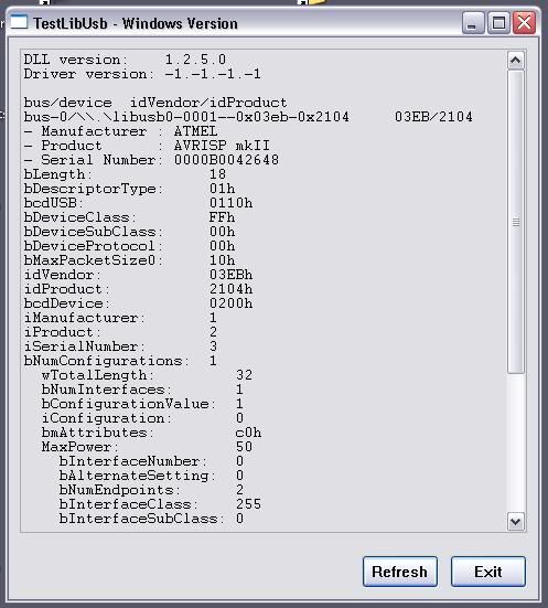
Time to find the address of the programmer. The AVRdude manual suggested a way of doing this for a different programmer (see example at bottom of this page). I tried this for the AVRISP, but with no success. Poking through the libusb start-menu group, I came across someting called "Test (Win) Program". This gave me the following screen:


I called AVRdude again, and instead of a port, I passed it the end of the serial number (as seen in the above page from the avrdude help) - and what do you know, I got a response!

Right, now what do I tell AVRdude to do to the chip? Well, the arduino bootloader page has a list of all the operations performed on a chip when the bootloader is burnt - I decided to use this as a template for what I needed to do.

The contents of \arduino-0018\hardware\Sanguino\boards.txt look like this:

##############################################################
sanguino.name=Sanguino

sanguino.upload.protocol=stk500
sanguino.upload.maximum_size=63488
sanguino.upload.speed=38400
sanguino.bootloader.low_fuses=0xFF
sanguino.bootloader.high_fuses=0xDC
sanguino.bootloader.extended_fuses=0xFD
sanguino.bootloader.path=atmega644p
sanguino.bootloader.file=ATmegaBOOT_644P.hex
sanguino.bootloader.unlock_bits=0x3F
sanguino.bootloader.lock_bits=0x0F
sanguino.build.mcu=atmega644p
sanguino.build.f_cpu=16000000L
sanguino.build.core=arduino
The ".bootloader" lines match the commands passed to the processor when programming. Looking in "Sanguino\bootloaders\atmega644p" lead me to the .hex file that is the bootloader. I moved this file to C:\avrdude\, as the version I installed here now worked (with the installation of libUSB).

Now that I had all the parts, I re-read the AVRdude help and composed a string that would perform all the operations that I needed: "avrdude -c avrispmkii -p m644p -P usb:48 -e -U lock:w:0x3F:m -U efuse:w:0xFD:m -U hfuse:w:0xDC:m -U lfuse:w:0xFF:m -U flash:w:ATmegaBOOT_644P.hex -U lock:w:0x0F:m"


Before trying to burn the bootloader, I used the -v switch to see if the ATmega 644P had a boot section. It does not, so the bootloader will be written to the flash.


It turns out that the string of commands was actually too long for the windows command prompt to handle in one go. I had to split the command up into single operations, which would help if something went wrong. I also added the -u switch to all the commands until I had finished writing the fuse bits - this stops AVRdude checking that the fuses are correct.


Here are the commands I used:


avrdude -c avrispmkii -p m644p -P usb48 -B 8 -u -e -U lock:w:0x3F:m -v
avrdude -c avrispmkii -p m644p -P usb48 -v
avrdude -c avrispmkii -p m644p -P usb48 -u -U efuse:w:0xFD:m -v
avrdude -c avrispmkii -p m644p -P usb48 -u -U hfuse:w:0xDC:m -v
avrdude -c avrispmkii -p m644p -P usb48 -u -U lfuse:w:0xFF:m -v
avrdude -c avrispmkii -p m644p -P usb48 -U flash:w:ATmegaBOOT_644P.hex -v
avrdude -c avrispmkii -p m644p -P usb48 -U lock:w:0x0F:m -v


The "-B 8" in the first line slows down the programmer by 8 microseconds. This is because the first time I tried to talk to the processor I got the error reported here. The second line is to check that the device now reports a correct signature, which it did.

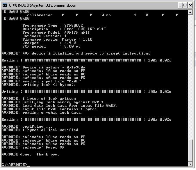
I called the commands in the order given above, and was greeted with success after each one. Here is the avrdude output from the last operation:

I was overjoyed that it worked - so much trouble for about 6 kb of data!

Now to see if it worked. I had downloaded and played with sprinter already, so I loaded it up into Arduino and clicked the "verify" button. It seemed to compile ok, so I clicked "upload".

After an antagonising wait:


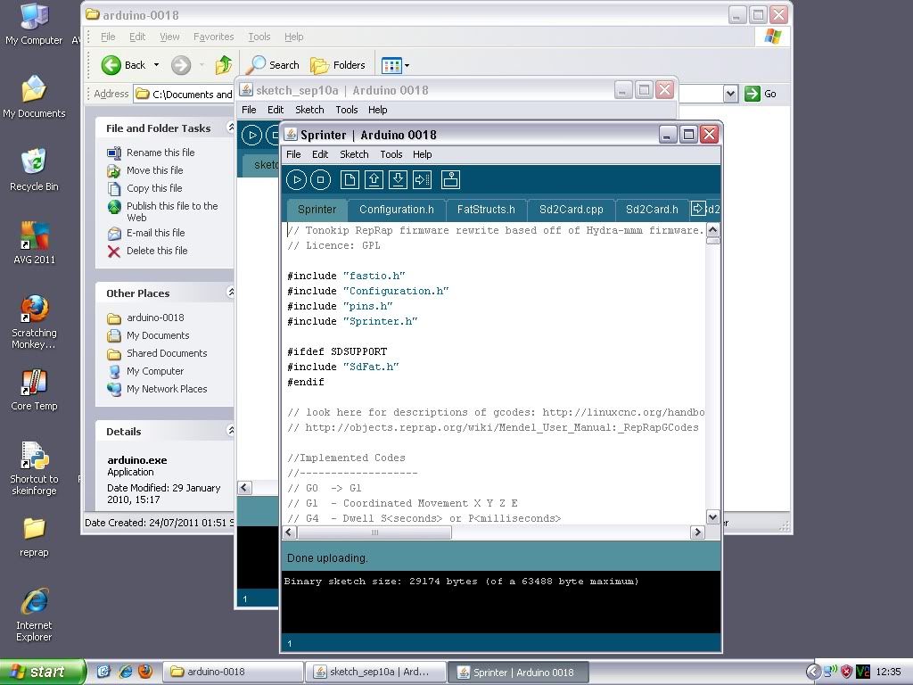
It uploaded OK! The bootloader was a success, and now I can program firmware to the board via the USB connection!

For some reason, Reprap host has now stopped working. I think it is to do with the comms being interrupted by something that I recently installed. I went off and grabbed version 0025 of replicatorG, because it was the first alternative that came to mind.

I connected everything up (Z-axis plugged in, PSU turned on and connected, USB lead to Bbernard), set ReplicatorG to use "klimentkip" as the communication protocol and told it to connect. After a short wait, I had a connection and everything was talking. I opened the control panel and asked the Z to move:


It went the wrong way. And only did it once before I have to reset the connection, but I'm sure I can fix these - in fact I have already inverted the Z-axis in the firmware and re-uploaded - Easy!

Next up - Building the extruder.